


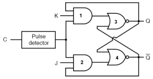
JK Flip Flop is an improved version of SR flip flop where the undefined state of SR Flip Flop is eliminated by providing feedback. Let us take a look at the JK flip-flop logic diagram. We can make JK flip-flops using NAND gates only. But here we have taken a circuit that uses AND and NOR gates just like we discussed in SR flip flop.
Also Check: Everything you need to know about flip flop

JK Flip Flop Working
Let us look at the possible cases and write them down in our truth table. The clock is always 1.
Case 1: J=0, K=0
Gate1 = 0, Gate2 = 0, Gate3/Q(n+1) = Q, Gate4/Q(n+1)’ = Q’
Note:
- Since one input of both gate1 and gate2 is 0 and both gates are AND gates, the output of both gates will be 0 irrespective of other inputs.
- Gate3 = (0+Q’)’ = (Q’)’ = Q
- Gate4 = (0+Q)’ = (Q)’ = Q’
Case 2: J=0, K=1
Gate1 = Q, Gate2 = 0, Gate3/Q(n+1) = 0, Gate4/Q(n+1)’ = 1
Note:
- Since both the inputs to Gate1 are 1 and gate1 is an AND gate the output of gate1 will be equal to the third input.
- Since one input of gate2 is 0 and gate2 is an AND gate, output gate2 will be 0 irrespective of other inputs.
- Gate3 = (Q+Q’)’ = 1’ = 0
Case 3: J=1, K=0
Gate1 = 0, Gate2 = Q’, Gate4/Q(n+1)’ = 0, Gate3/Q(n+1) = 1
Note:
- Since both the inputs to Gate2 are 1 and gate2 is an AND gate the output of gate2 will be equal to the third input.
- Since one input of gate1 is 0 and gate1 is an AND gate, output gate1 will be 0 irrespective of other inputs.
- Gate4 = (Q’+Q)’ = 1’ = 0
Case 4: J=1, K=1
Gate1 = Q, Gate2 = Q’, Gate4/Q(n+1)’ = 0, Gate3/Q(n+1) = Q’
Note:
- Since one input of both gate1 and gate2 is 0 and both gates are AND gates, the output of both gates will be equal to the third input.
- Gate4 = (Q’+Q)’ = 1’ = 0
- Gate3 = (Q+0)’ = Q’
Now let us write the truth table-
JK Flip-Flop Truth Table
| J | K | Q(n+1) | State |
| 0 | 0 | Qn | No Change |
| 0 | 1 | 0 | RESET |
| 1 | 0 | 1 | SET |
| 1 | 1 | Qn’ | TOGGLE |
We will use this truth table to write the characteristics table for the JK flip-flop. In the truth table, you can see there are two inputs J and K, and one output Q(n+1). But in the characteristics table, you will see there are three inputs J, K, and Qn, and one output Q(n+1).
From the logic diagram above, it is clear that Qn and Qn’ are two complementary outputs that also act as inputs for Gate3 and Gate4, hence we will consider Qn i.e. the present state of Flip flop as input, and Q(n+1) i.e. the next state as output.
After writing the characteristic table, we will draw a 3-variable K-map to derive the characteristic equation.
| J | K | Qn | Q(n+1) |
| 0 | 0 | 0 | 0 |
| 0 | 0 | 1 | 1 |
| 0 | 1 | 0 | 0 |
| 0 | 1 | 1 | 0 |
| 1 | 0 | 0 | 1 |
| 1 | 0 | 1 | 1 |
| 1 | 1 | 0 | 1 |
| 1 | 1 | 1 | 0 |
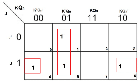
From the K-map you get 2 pairs. On solving both we get the following characteristic equation:
Q(n+1) = JQn’ + K’Qn
Advantages of JK Flip-Flop
There are several advantages to using a JK flip-flop. Some of them are listed below:
- Toggle capability: It has a toggle capability, which means that it can be used to create a circuit that toggles between two states.
- No invalid states: Unlike the SR flip-flop, the JK flip-flop does not have any invalid states.
- Reduced race conditions: It is less susceptible to race conditions than the SR flip-flop, which can lead to more stable circuit operation.
- Bi-stable operation: Like the SR flip-flop, the JK flip-flop has a bi-stable operation, which means that it can hold a state indefinitely until it is changed by an input signal.
Limitations of JK Flip-Flop
Apart from several advantages, there are some limitations associated with JK flip-flops. Some of them are listed below:
- Complexity: The JK flip-flop is more complex than some other types of flip-flops, which can make it more difficult to design and implement in digital systems.
- Power consumption: The JK flip-flop can consume more power than other types of flip-flops, especially when used in toggle mode.
- Propagation delay: The JK flip-flop has a propagation delay, which can lead to timing issues in digital systems with tight timing constraints.
- Limited scalability: The JK flip-flop can be difficult to scale up to more complex digital systems, as it can lead to increased complexity and the potential for errors.
JK Flip Flop Applications
Some of the applications of JK flip-flop in real-world includes:
- Counters: The JK flip-flop can be used in conjunction with other digital logic gates to create a binary counter. This makes it useful in real-time applications such as timers and clocks.
- Data storage: The JK flip-flop can be used to store temporary data in digital systems.
- Synchronization: The JK flip-flop can be used to synchronize data signals between two digital circuits, ensuring that they are operating on the same clock cycle. This makes it useful in applications where timing is critical.
- Frequency division: The JK flip-flop can be used to create a frequency divider, which is a circuit that divides the frequency of an input signal by a fixed amount. This makes it useful in real-time applications such as audio and video processing.
