


The main purpose of this article is to help design engineers in selecting the right battery management and charging IC and completing their proof of concept (PoC) phase. The resources provided include schematics, bill of material (BOM), design files, GUI interface software, etc
The lithium-ion (Li-ion) cell is one of the most common energy sources in today’s battery-driven world. Li-ion cells have good energy density and can be recharged. But they are very volatile and thus require specialised chargers to keep the battery and device safe.
The main purpose of this article is to help design engineers in selecting the right battery management and charging IC and completing their proof of concept (PoC) phase. The resources provided include schematics, bill of material (BOM), design files, GUI interface software, etc.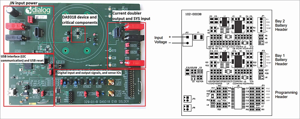

All the reference designs in the article can be used as independent cell chargers. Some of the designs are small enough to be integrated into a product as a sub-system for charging an in-built battery.
In this article, we will discuss the essential parameters of each of the Li-ion chargers. Table 1 lists the important parameters of all the charging reference designs.
| What is a Reference Design? |
|
Wikipedia defines a reference design as a technical blueprint of a system that is intended for others to copy. The main purpose of the reference design is to support companies in the development of next-generation products using the latest technologies. The reference product is proof of the platform concept and is usually targeted for specific applications. It enables a fast track to market, thereby cutting costs and reducing risk in the customer’s integration project.
|
TIDA-00590 for fast charging with low thermal budget
The TI TIDA-00590 is a fast charger reference design module from Texas Instruments. It is capable of fast charging a single Li-ion cell with 5A charge current with low thermal budget. The circuit design has been tested by TI and uses the EVM GUI and getting started guide.
TIDA 00590 utilises two charging ICs marked as U1 and U2 in a dual IC configuration, which provides more than their 5A maximum charge current and distributes the heat loss across the board more efficiently. The charging IC bq25890/2 is a highly integrated 5A switch-mode battery charge management and system power path management device for single-cell Li-ion and Li-polymer batteries.
To achieve higher efficiency, the module offers a low impedance power path, which also reduces battery charging time while extending the battery life during discharging phase. The IC also integrates input current optimiser (ICO) and resistance compensation (IRCOMP) to deliver maximum charging power to the battery.
The module is over 90% efficient with a maximum efficiency of about 94%. The efficiency of the charger decreases as the charge current is increased.
This device supports various input sources, which include a standard USB host port, USB charging port, and USB compliant adjustable high voltage adaptor. Furthermore, it uses MaxCharge handshake using D+/D– pins and DSEL pin for USB switch control.
The device is compliant with USB 2.0 and USB 3.0 power specs with input current and voltage regulation. The charger features multiple safety features, including battery temperature negative thermistor monitoring, charging safety timer, overvoltage/overcurrent protections, undervoltage protection, and over-discharge protection.
The charger also employs a TS3USB221A, which is a high-bandwidth switch that requires a 3.3V supply. Since there are two charging ICs with a single USB I/O for the charger, both the power management ICs need to work in sync and need to transfer data simultaneously. Therefore, there’s a need for a USB hub or controllers.
The TS3USB221A solution can effectively expand the limited USB I/O by switching between multiple USB buses to interface them to a single USB hub or controller. The switch works as a multiplexer; it takes a single USB input and gives output to both the bq25890/2 charging ICs. To provide a 3.3V output to the TS3USB221A, an LDO LP2985AIM5-3.3/NOPB is used.
mepr-show rules=”144188″ unauth=”both”]
| Company | Module | Charge Management IC | No. of Cells | Suitable Chemistry | Max Charge Current (in amps) |
Input Voltage (in volts) |
Registration Required
|
| Texas Instruments | TI TIDA-00590 | BQ25890/2 | 1S | Li-ion/Li-Po | 5A | 3.9-14 | No |
| Microchip | MCP1630 | MCP1630 | 1S or 2S | Li-ion/NiCD/NiMH | 2A | 10-28 | Yes |
| Monolithic Power | EV2639A-R-00B | MP2639A | 2S | Li-ion | 2.5A | 4.0-5.75 | No |
| ADI | ADI DC2703A-A-KIT | LT8491 | Multi-configuration | Li-ion, LiPo, SLA, etc | 16.6A (@12V) | 17-54 | No |
| Maxim Integrated | MAXREFDES1219 | MAX14746 | 1S | Li-ion | 3A | 2.2-5.5 | Yes |
| Renesas | DA9318 Reference board | DA9318 | 1S | Li-ion | 10A | 4.3-24 | No |
Important components:
U1 – BQ25890RTWR charging management IC
U2 – BQ25892RTWR charging management IC
U3 – TS3USB221A high-bandwidth switch
U4 – LP2985AIM5 LDO
Features:
- Fast charges a smartphone on PCB with a low thermal budget
- Charge currents >5A
- This circuit design is tested and uses the EVM GUI and getting started guide
- High efficiency
- Integrated ADC
- Power path
- USB C/PD compatible
- USB D+/D-/BC1.2 integrated
- USB OTG integrated
- Operating voltage 3.9V-14V
- I2C communication
- LED indication for status signals
- Test points for key signals available for testing purposes
- Jumpers for different circuit configuration
Protection features:
- BAT temp thermistor monitoring (JEITA profile)
- BAT temp thermistor monitoring (hot/cold profile)
- IC thermal regulation
- Bad adaptor detection
- ICO (input current optimisation)
- IINDPM (input current limit)
- Input OVP
 The module is suitable for use in mobile phones, cameras, tablets, standalone chargers, etc. You can find all the resources for TIDA 00590 by scanning the QR code.
MCP1630 multi-bay charger for 2S configuration
The MCP1630 Li-ion charger is a versatile charger design capable of charging up to two single-cell Li-ion battery packs in a parallel configuration. The power train used for the MCP1630 is a SEPIC. The module can take inputs anywhere from 10V to 28V and up to 16 modules can be daisy-chained for charging additional cells.
The MCP1630 multi-bay Li-ion charger has the flexibility to optimise the charging algorithm for new battery technology and add proprietary features by coding the microcontroller. The charger offers multiple charging features, such as input overvoltage protection, battery overvoltage protection, thermal shutdown, battery-temperature monitoring, and battery-pack fault monitoring. It can also detect the status of the battery along with the insertion and removal of the battery pack.
The brain of the charger is PIC18F2410. which is an enhanced flash microcontroller with 10-bit A/D. The microcontroller runs at a frequency of 40MHz and provides high computational performance along with lower power consumption.
The reference design also has programming header pins required for updating the firmware of the microcontroller. It also employs a dual op-amp MCP6292. The battery charger automatically detects the insertion or removal of a battery pack.
Important components:
U1, U4 – MCP1630 charging IC
U2, U5 – MCP6292 dual op-amp MSOP8
U3, U6 – SN74LVC1G66DBVR bilateral switch
U7 – NC7SZ74K8k D-type flip-flop
U8 – PIC18F2410 8-bit CMOS microcontroller
U9 – SN74LVC2G14DBVR dual inverter
Features of MCP1630:
- Programmable parameters modified in firmware
- The MCP1630 multi-bay Li-ion charger has the flexibility to optimise the charging algorithm for new battery technologies and add proprietary features by coding the microcontroller
- Controlled soft-start
Safety features:
- Overvoltage protection (battery removed)
- Overcharge protection to prevent the battery from becoming dangerously overcharged
- Overcurrent protection in the event of a shorted battery
- Battery reversal protection
- Input short-circuit protection
- Overtemperature protection to prevent the battery from reaching too high a temperature during charge
- Fast charge termination if the battery temperature is outside a preset window
- Controlled soft-start
The module is suitable for charging a Li-Ion battery pack. You can find more details and design resources by scanning the QR code.
EV2639A-R-00B 2S cell charger with integrated boost converter
The EV2639A-R-00B from Monolith Power is the reference design board for the MP2639A, which is a 2-cell battery charge management system. MP2639A is a highly integrated, flexible switch-mode charge management IC that can take input between 4V and 5.75V and charge 2S Li-ion and Li-Po cells. The module is capable of charging 2S cell with 2.5A charge current.
The reference module works in a charge mode and based on the state of the input it determines the management of the system and battery charging. The module also provides voltage based fuel gauge indication through four LED drivers present in the circuit.
The MP2639A IC is highly programmable, whose input voltage and current can be controlled by updating the firmware. It gives an option of enhancing the discharge current up to 5A. The board offers multiple safety features, which include input overvoltage protection, battery overvoltage protection, thermal shutdown, battery temperature monitoring, and a programmable timer to prevent prolonged charging of a dead battery.
In this reference design, the MP2639A works in a step-up mode to charge the 2-cell battery from the 5V input. In absence of the charger, the module is in discharge mode, where it works in a step-down mode to give an output of 5V. For the charging function, the battery charging IC detects the battery voltage and based on the voltage charges the battery in three phases: trickle current, constant current, and constant voltage.
Features:
- Bidirectional operation for charging or discharging
- 2-cell Li-ion or Li-polymer charging
- Cell balance and protection escorting for two-series cell charging
- Light-load detection for discharge mode
- Integrated voltage based fuel gauge using four LED drivers
- Takes 5V input and charges 2S cell
Safety features:
- Input overvoltage protection
- Battery overvoltage protection
- Thermal shutdown
- Battery temperature monitoring
- Programmable timer to prevent prolonged charging of a dead battery
This charger reference design can be used in various devices, including mobile, tablets, power stations, mobile internet devices, and standalone Li-ion battery chargers. You can find additional details and the design resources by scanning the QR code.
ADI DC2703A-A-KIT battery charger with MPPT and telemetry
The DC2703A-A-KIT from Analog Devices is a reference design for a Li-ion battery charger with maximum power point tracking (MPPT) and telemetry. It employs IC LT8491 for charging and management of Li-ion battery and DC1613A, a USB to I2C controller, for enabling communication.
The board is configured for a wide range of input voltages from 17V to 54V and is suitable for various power sources, which include various DC sources like solar panels with 36 to 72 cells with a total power of up to 200W. The module has both buck and boost configurations, thus it can take input voltage below, above, or equal to the battery voltage. Apart from the Li-ion batteries, the charger is suitable for various other battery chemistries, including the flooded and sealed lead-acid batteries.
The datasheet indicates that the charger is up to 97% efficient when charging with a current of 6A. The efficiency of the charger decreases as the charging current increases.
The one feature which sets it apart from any other product is the MPPT for solar-powered applications. The on-chip logic of LT8491 IC enables true MPPT function, which continuously tracks the maximum power point at all times. In order to select the maximum value on the power curve, it periodically sweeps the input panel voltage.
The LT8491 includes a slave I2C compatible interface for digital control of the charger settings and digital readouts of charger telemetry and status. The module is compatible with an MS Windows based GUI application called simpleLT8491, which enables the user to monitor and control the telemetry and status data of the charger and battery pack in real time.
The DC2703A-A-KIT is capable of supporting higher current and voltage for different cell configuration by replacing the input side MOSFETs and capacitors with ones with higher ratings.
Important components:
U1 – ADI LT8491 battery charge controller IC
U2 – ADI LT1636CS8#PBF op-amp
U3 – ADI LTC4359CDCB ideal diode controller, 6-pin DFN EP
U4 – 24LC025-I/ST memory EEPROM, 2kb
Features of DC2703A-A-KIT:
- Operation from solar panel or DC supply
- VIN range: 17V to 54V
- VBAT range: 1.3V to 80V
- Single inductor allows VIN above, below, or equal to VBAT
- Automatic MPPT for solar powered charging
- Automatic temperature compensation
- I2C telemetry and configuration
- Remote sensing of battery voltage
This charger reference design can be used as a solar charger or a standalone charger for multiple cell chemistries, which include Li-ion, LiPo, and SLA. More details about the reference design can be viewed by scanning the QR code.
MAXREFDES1219 – a USB BC 1.2 compliant design
The MAXREFDES1219 is an integrated charger design for the 1-cell Li+ battery. The module is an optimum charger for both charging and monitoring. For charging management, it employs MAX14746 IC, which is a USB charger that integrates a charger detector, linear regulator, and smart power selector to provide up to 2A of charging current.
The module offers features such as USB charger detection and battery cell monitoring, which includes state of charge, open circuit voltage, temperature, current, etc. The reference design is compliant with USB Battery Charging Rev1.2, which is capable of detecting different battery charging methods, including standard downstream port, charging downstream port, and dedicated charging port. The devices also detect common proprietary charge adaptors, including those from
Apple 1.
This reference design uses Maxim Integrated’s MAX17260 fuel gauge IC, which employs the ModelGauge m5 algorithm that offers high estimation accuracy and has a low power consumption. The charger enables the user to set the charge termination voltage between 4.05V and 4.6V.
The MAXREFDES1219 can be configured quickly and easily by using the GUI software provided by the company. It requires a MAX32660EVSYS breakout board for connecting it with the PC. The MAX32660 module can enable read and write control of the two MAX14746/MAX17260 registers through the I2C interface.
The GUI’s demo view window displays the status and enables the control of both the charger and the fuel gauge monitor. The software is easy to use and automatically detects the hardware on making the connection.
Important components:
U1 – MAX14746 charging IC
U2 – MAX17260 fuel gauge IC
Features:
- USB Battery Charging Rev. 1.2 compliant
- Capable of detecting proprietary charger, such as Apple 1
- Simple GUI for monitoring and controlling the parameters
- Max current 2A
- Monitors from 1S battery cell
- Windows 10 compatible software
- I2C serial interface
- State of charge measurement
Safety features:
- Charger detection
- JEITA charge protection
- Thermal protection
- Battery cell monitoring
- Open circuit voltage
- Temperature monitoring
- Current monitoring
The reference design can be used for various applications, which include portable consumer devices, digital imaging devices (DSC, DVC), portable industrial devices, USB 1-cell pack equipment, etc. More details about the reference design can be viewed by scanning the QR code.
DA9318 – 10A fast battery charger
DA9318 from Renesas is a Li-ion fast cell charger reference design that can be used as a standalone 1S charger or can be implemented into laptops, smartphones, tablets, etc. The charger module employs an ATMEL SAM3U microcontroller as the USB transceiver. This adds the I2C functionality to the board and also the discrete digital IO control GPIO and dedicated functions.
The charge management IC DA9318M is capable of providing a maximum charging current of 10A. The charger is capable of charging with up to 98% efficiency delivering 2A charge current. This charger employs a high-efficiency current doubler with an integrated ADC for system monitoring.
The reference design is capable of handling current up to 10A while maintaining the safety of the battery. It operates together with the main charger, which handles the pre-charge and constant voltage charging duties. The charger is capable of delivering up to 6A current by using the standard Type C cable. The fast charging is achieved by the doubler circuit that uses a high-efficiency capacitive divider. The output voltage it provides is given by VIN/2.
The module has multiple safety features, which include an integrated reverse protection that blocks current flow in both the directions when the device is in off state. The DA9318 employs six hardware based safety functions for any undervoltage or overvoltage condition. All safety-triggered events lead to an automatic shutdown and are reported via an interrupt to the system.
It employs an 8-bit ADC to keep a check on parameters such as input current, output current, voltage, and junction temperature. For software supervision a programmable watchdog timer and for battery overload protection a safety timer are included.
The module employs two power monitoring INA226 ICs, which enable the measurement of the main charger input voltage and input current and allows the monitoring of the battery parameters. I2C protocol is used for communication.
When the charge current reaches a handover charge current threshold, which is arbitrarily set to 0.9A, the DA9318 is switched off and the main charger is enabled and finishes off the charge cycle. The module is over 98% efficient when supplying an output current of 0.9A.
Important components:
U1 – DA9318 charging IC
U2 – ATMEL SAM3U microcontroller
Features:
- Safe high-voltage direct charging
- Travel adaptor detection
- User programmable overcurrent ptotection threshold
- Built-in fault protection
- High immunity of false triggering under transients
- Responds to input overvoltage in less than 1µs
- Fault indication for various fault occurrences
- 10A output current (DA9318M)
- 98% efficiency at 2A
- 10% current sense accuracy (DA9318M)
- Reverse and forward current protection in IDLE mode
- I2C compatible 2-wire interface

Safety features:
- Automatic shutdown in fault condition
- High-accuracy protection thresholds
- Overcurrent protection
- Reverse and forward current protection in IDLE mode
- Junction temperature monitoring
This charger reference design can be used in various devices, including mobile, standalone Li-ion battery chargers, tablets, larger battery packs, laptops, etc. More details about the reference design can be found by scanning the QR code.
The author, Sharad Bhowmick, works as a Technology Journalist at EFY. He is passionate about power electronics and energy storage technologies. He wants to help achieve the goal of a carbon neutral world.
[/mepr-show]
