


 Here is a simple, low-cost project to control the speed of a DC motor linearly for specific and precise applications. Normally, pulse-width modulation (PWM) is used for varying the speed of DC motors. When width of the pulse is fixed, the speed of motor remains the same, and when its width changes, the speed also changes.
This project uses a low-cost Audino Uno board with few external components. The circuit converts the switch-on time to linear variation in speed with forward-reverse control.
Generally, small DC motors are used to screw-unscrew, drill PCB holes, and for precision grinding, etc. In most of these applications, you need low speed in the beginning that increases with time. Low speed at the beginning enables you to correct the positioning of the workpiece and the tool.

Generally, a rotary potentiometer is used to control speed of a DC motor as shown in the module in Fig. 1. But with this proposed speed controller the user can concentrate on drilling or screwing rather than on varying the speed with potentiometer.

Also, there are wear and tear issues in a linear potentiometer that lead to improper contact and malfunctioning of the device after some time. Potentiometers are good but have following fundamental problems:
1. Due to rapid cycling, the inner materials wear out due to friction
2. The wiper movement causes ‘fader scratch’ noise
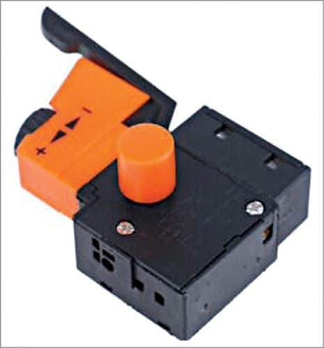
3. In some cases, linear/sliding potentiometers (high-end drill machine trigger switch) are used for speed control at the trigger point of a motor. In such cases, speed of the motor is proportional to the depth or pressure at the triggering point. An example of speed control tigger switch used in electric hand drilling machine is shown in Fig. 2.
This circuit converts the switch-on time to speed of the DC motor. So, the speed of the motor increases linearly from zero, till you keep the on/off switch pressed, to its maximum speed.
Circuit and working
Fig. 3 shows block diagram of the time based speed control switch for DC motor. A 12V DC power supply with rated current sufficient to drive the Arduino Uno board and motor is used. The supply is connected through 12mm power jack to Arduino board.
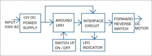
Slow incremental speed of a DC motor is difficult to achieve using discrete components and timing ICs. But here simple on/off pushbutton switch S1 is connected as an input. LED1 connected to pin 9 of Arduino acts as speed indicator. As you continue pressing the switch, the brightness of LED1 increases and so does the speed of DC motor.
The circuit interfaces the PWM signal generated from the Arduino Uno to the 12V DC motor that is being driven. Forward-reverse switch S2 is used for changing the direction of rotation of the motor.
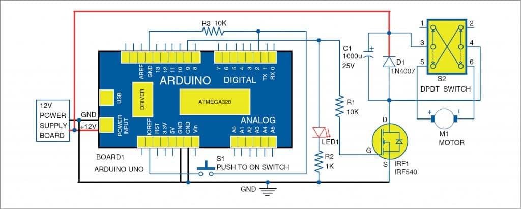
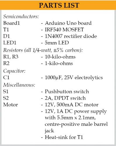
Fig. 4 shows circuit diagram of the time based speed control switch for DC motor. Pin 2 of Arduino Uno Board1 is connected to 5V/IOREF pin through pushbutton switch S1. Digital pin 2 of Arduino and switch S1 are connected to ground through common 10-kilo-ohm resistor R3. Pin 9 of Arduino Uno acts as the output pin, which is also connected to gate of IRF540 MOSFET (T1). MOSFET suits best in PWM applications rather than a transistor.
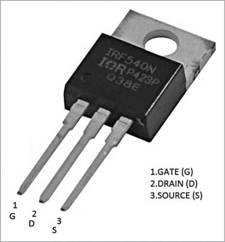
The pin-outs of IRF540 are shown in Fig. 5. The drain is connected to 12V DC supply via diode D1, which protects the circuit during motor power on and off conditions. Capacitor C1 (1000µF, 25V) acts as a smoothing device. DPDT switch S2 connected between diode D1 and motor is used as a forward-reverse switch.
For the prototype, a small 12V DC motor having 500mA rating and a 2A DPDT switch were used. A 12V, 1A power supply was used for the prototype. The ratings of 12V DC power supply, MOSFET, diode D1, and DPDT switch S2 are decided based on ratings of the DC motor.
Software
The circuit uses software program Time2SpeedSwitch.ino written in Arduino programming language that is loaded into the internal memory of Arduino Uno. ATmega328P on Arduino Uno comes with a pre-programmed boot loader that allows users to upload a new code to it without using a peripheral hardware programmer. Arduino IDE 1.6.4 is used to compile and upload the program. The sketch (software) is the heart of the system and carries out all the main functions.
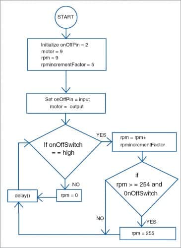
The program is simple and easy to understand. Comments are given at the end of each command line. Input and output pins are initialised. The rpmIncrementFactor is a numeric value representing the rate of increase of the motor speed in steps. The value is user-defined and can be set as per requirement.
The delay( ) function determines the rate at which the speed of the motor increases. For increasing speed, decrease the delay value, and vice versa. For better understanding of the program code its flowchart is shown in Fig. 6.
Download Source Code
Construction and testing
The circuit, including Arduino Uno board and other peripheral components, can be placed in a 10cm x10cm box with a 12V DC jack for power supply input. A PCB layout suggested for the circuit is shown in Fig. 7 and its component layout in Fig. 8.
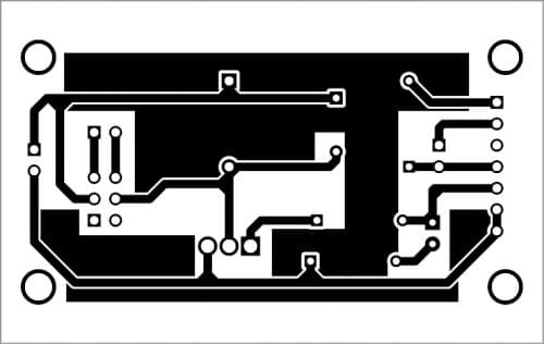

Download PCB and Component Layout PDFs: click here
Switches S1 and S2 can be placed near the motor at your convenience. LED1 can be on the front panel for visual indication.
Connect a multimeter across pin 9 and GND pin of Arduino to observe numerical incremental voltage on it. This value corresponds to the speed of the DC motor.
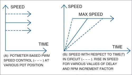
The graph shown in Fig. 9(A) represents the change in speed of the motor with respect to change in position of the potentiometer. Graph in Fig. 9(B) represents the change in speed of the DC motor with respect to time after the switch S1 is pressed.
Precautions. Arduino Uno boards are highly sensitive, so handle it carefully. Check the correct input polarity of DC power supply jack (2.1mm centre-positive plug into the board’s power jack). Use a suitable heat-sink for MOSFET T1.
K. Murali Krishna works as junior engineer at BSNL, Rajahmundry, Andhra Pradesh. He is an electronics enthusiast, circuit designer, and technical writer
