


This article aims to revive Lisp programming language for native, interactive and incremental microcontroller (MCU) program development by running a dialect of Lisp programming (PicoLisp) as virtual machine on the target. It also demonstrates the power of Lisp through execution of expressive Lisp programs on a 32-bit MCU.
Lisp programming offers a practical mathematical notation to write computer programs, mostly influenced by lambda calculus. It is still the most-favoured programming language for artificial intelligence research.
Dynamic languages like Lisp have been in existence as a versatile tool for rapid application development. Many interesting, practical embedded solutions have been developed so far with such languages, supported as part of a virtual machine (VM). Fig. 1 shows the system architecture of a natively-programmable, digitally-controlled system.

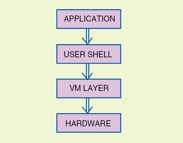
With the above architecture, it is possible to write abstract, self-adapting, middle-level drivers for hardware modules on the MCU. This enables the possibility of platform-independent, native embedded software development.
Lisp programming is the second-oldest high-level programming language (the first being FORTRAN). Linked lists are one of its major data structures. A program written in Lisp is constructed with lists. One of the most interesting properties of this language is its homo-iconic nature.
Although projects like PICOBIT and ARMPIT Scheme already implement a compact Lisp programming language for an MCU, there are many reasons to consider PicoLisp for programming MCUs.
PicoLisp is constructed as a VM. It is written in portable C and is easily extendable. After much research and programming to narrow down on a Lisp programming implementation, PicoLisp was chosen as a VM for the following reasons:
1. Dynamic data types and structures
2. Formally homo-iconic
3. Functional programming paradigm
4. An interactive REPL(read-eval-print loop)
5. Pilog, a declarative language with semantics of Prolog in PicoLisp
6. Small memory footprint
7. Permissive, non-copyleft free software licence
At the lowest level, PicoLisp programs are constructed from a single data structure called cell. A cell is a pair of machine words, which are traditionally called CAR and CDR in Lisp programming terminology. These words can represent either a numeric value (scalar) or address of another cell (pointer). All higher-level data structures are built out of these cells.
Basic data types that PicoLisp supports are numbers, symbols and lists. As a result, it is one of the fastest Lisp dialects available, since only fewer options are checked at runtime to parse a value.
PicoLisp in addition supports an integrated database system. This is a huge advantage for embedded system applications that require a convenient facility to perform data transactions.
Overall logical software structure for running full-fledged PicoLisp on the MCU is shown in Fig. 2. It shows the communication between PicoLisp VM and various other modules in code base.
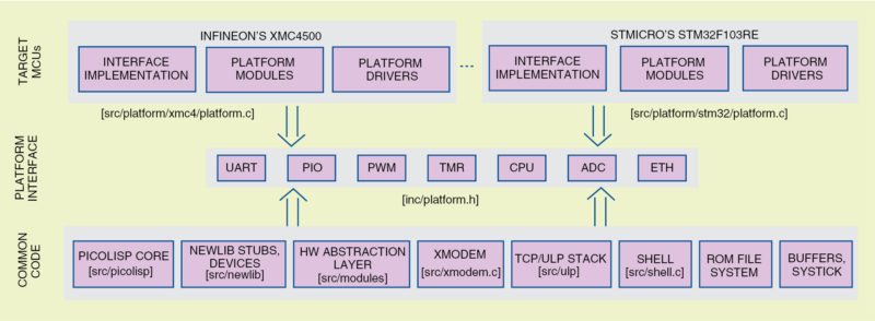
The code base remains highly portable across various platforms and architectures simply by using the following key principles:
1. Code that is platform-independent is common code and should be written in portable ANSI C as much as possible. PicoLisp itself is a part of the common code section and is written in this way.
2. Code that is not generic (mostly peripheral and CPU-specific code) must still be made as portable as possible by using a common interface that must be implemented by all platforms on which PicoLisp runs. This interface is called platform interface.
3. Platforms vary greatly in capabilities. The platform interface tries to group only common attributes of different platforms.
Platform interface is declared in inc/platform.h header file from source distribution. It is a collection of various components like UART, SPI and timers. Each component has an identifier, which is a number that identifies that component in PicoLisp. Generally, numbers are assigned to components in their natural order. For example, Port A will have identifier value 0, Port B will have 1 and so on.
Similarly, second SPI interface (SPII) of the MCU will probably have an identifier value of 1. Pin 0 in Port 1 on Infineon XMC4500 will be called ‘P1_0 in PicoLisp. Similarly, pin 27 in Port B on Atmel AT32UC3A0256 will be called ‘PB_27 (notice the single opening quote).
Some issues
PicoLisp cannot be directly compiled for a 32-bit RISC machine. There are many issues to address before one can use PicoLisp REPL over UART or TCP/IP interface on the MCU. For instance, supporting programs such as memory allocators are required for PicoLisp to function correctly. We use Newlib C library and implement stubs of code for the memory allocator. We have to deal with issues like routing plain I/O over UART or TCP/IP interface of the MCU.
We also require support for a multimedia card memory interface to store PicoLisp programs. We can then load PicoLisp programs at runtime. This implies a requisite for a file system. We also need to implement stubs of code for file I/O support over SPI protocol. For the file system, we use FatFs FAT file system module.
Once all supporting programs are in place, getting PicoLisp to run on the MCU is then fairly straightforward. On account of its small size, it can be easily embedded on an MCU in less than 256kB of flash. It can also be easily compiled for a given architecture with a toolchain like GNU gcc. Currently, a Python based build system called SCons is being used to compile the code base.
Booting PicoLisp on the MCU
Given below is the sequence of events that occur after the MCU is powered up. The platform-initialisation code is executed. This program does very low-level platform setup, copies ROM contents to internal RAM, zeroes out BSS section, sets up the stack pointer and long jumps to the main function.
1. The main function calls the platform-specific initialisation function and returns a result that can be either a value indicating success or failure. If it fails, main instantly gets blocked. A debugger can then inspect the internals of the state machine.
2. The main function then initialises the rest of the system: ROM file system, XMODEM and terminal support.
3. If files /rom/autorun.l or /mmc/autorun.l exist, these are executed. If one file is found before the other, it terminates further execution of the other file and the context jumps to the next step. If it returns after execution, or if files are not found, boot process continues with the next step.
4. If boot parameter is set to standard and the shell was compiled in the image, it is started. In the absence of the shell, standard PicoLisp server is started.
PicoLisp for MCUs
PicoLisp can be compiled to either support a user console over UART (the default and by far the most popular) or a console over TCP/IP. It can run on a wide variety of MCUs. Some practical aspects of using PicoLisp are listed below:
1. Code base is hardware independent. It proves to be extremely portable across different architectures.
2. Programs in PicoLisp are highly adaptable, field programmable and re-configurable for a variety of practical applications.
3. Lisp Programming the MCU follows a very natural iterative process because PicoLisp permits the user to develop programs in an interactive and incremental way. The code supplies various tools to aid in native Lisp programming (like an onboard vi-clone text editor and XMODEM implementation to share files).
4. PicoLisp is a very extensible piece of software. Adding support for newer peripherals or modules is a naturally-smooth process.
5. Code bears a royalty-free, permissive, non-copyleft free software licence. This permits code reuse within a proprietary digital base.
Examples with Mizar32 board (Lisp Programming)
Mizar32 development board (Fig. 3) is a low-cost, stackable multi-board computer designed and produced under Free Hardware Licence by SimpleMachines. It is composed of a base module with Atmel AVR32 AT32UC3A0256 system-on-chip processor running at 66MHz with 32MB of SDRAM, 64kB SRAM, 256kB of flash memory, SD card slot, USB port and JTAG connector. A range of add-on boards can be stacked on its bus connectors to provide a serial port, a character based LCD display, VGA/mouse/keyboard/audio board, Ethernet and so on.
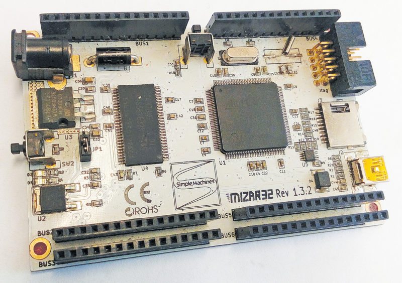
It runs PicoLisp (Lisp programming) as its standard software, allowing fast production of custom solutions.
Mizar32 is shipped with PicoLisp interpreter programmed into flash, including support for the optional TCP/IP networking module.
Mizar32 can also be programmed by the end user with different, customised versions of PicoLisp, FreeRTOS or with other stand-alone programs.
Once we have PicoLisp running on the board, you can access all MCU peripherals from Lisp. There are three Mizar32 variants, namely, A, B and C. These use AT32UC3A0512, AT32UC3A0256 and AT32UC3A0128 chips, respectively. SDRAM interface is the same for all three, which is 32MB. The difference is in flash size. Otherwise, the board layout, memory layout is the same.
Let us now see two examples:
Toggling LED. A simple PicoLisp program (led.l) is listed below that toggles an LED using a user button on Mizar32 board. Quoted symbols PB_29 and PX_16 are PicoLisp symbols that correspond to pin 29 on Port B and pin 16 on Port X, respectively. Parsing of these values is done in the generic PIO Lisp module (via hardware-abstraction layer). Transient symbols *pio-output* and *pio-input* are used to set directions to the port pins. A simple infinite loop reads the button on the input pin and toggles the LED if pressed.
[stextbox id=”grey”]# A sample for user-buttons.
# Declare pins
(setq led ‘PB_29 button ‘PX_16)
# A simple delay function
(de delay (t)
(tmr-delay 0 t) )
# Make sure the LED starts in
# the “off” position and enable
# input/output pins
(de init-pins ()
(pio-pin-sethigh led)
(pio-pin-setdir *pio-output* led)
(pio-pin-setdir *pio-input* button) )
# And now, the main loop
(de prog-loop ()
(init-pins)
(loop
(if (= 0 (pio-pin-getval button))
(pio-pin-setlow led)
(delay 100000)
(pio-pin-sethigh led)
(delay 100000) ) ) )
(prog-loop)[/stextbox]
Reaction timer. This program (timer1.l) measures the time taken to press a key on the keyboard after the program is run. Time will be displayed on the terminal. Try it a few times and then see results. Also compare results with others who have tried this before you:
[stextbox id=”grey”]# A reaction timer in picolisp
(de reaction-timer ()
(prinl “Welcome to the reaction timer.
When I say Go!, enter a character.”)
(prinl “Press q [Enter] to quit.”)
(setq
timer *tmr-sys-timer*
answer “” )
(until (=T answer)
(println “Ready?”)
# Wait for a random time
from 2 to 5 seconds
(tmr-delay timer (+ 2000000 (rand 1
3000000)))
(println “Go!”)
(setq
start-time (tmr-read timer)
answer (read) # wait for them to
enter any character
end-time (tmr-read timer) )
(println “You reacted in “ (tmr-
gettimediff timer start-time
end-time)
“ microseconds”) ) )[/stextbox]
Testing the examples (Lisp Programming)
We have stored the above two source codes (led.l and timer1.l) in a memory card as explained in this section. To test these two examples, you need Hempl software along with gcc, SCons, dfu-programmer and minicom software running on your Linux system. For this, follow the steps given below:
Installing Hemple software. Get the latest Hempl distribution from github. Make a working directory, say, hacking, for this on your Linux machine (Ubuntu version 13.04)
[stextbox id=”grey”]$ cd hacking
$ git clone www.github.com/
simplemachines-italy/hempl.git
$ cd hempl[/stextbox]
Now, you should be in Hempl directory.
Installing gcc for AVR32. We require a gcc for AVR32 device. Get that from www.en.wikibooks.org/wiki/Hempl/Compiling_Hempl. Select Install an AVR32 cross-compiler/Fetching and unpacking the toolchain. Follow the instructions and get the toolchain installed.
Place the toolchain in home directory. It could be something like:
[stextbox id=”grey”]/home/avr32-gnu-toolchain-linux_x86/[/stextbox]
From Hempl directory, make sure the toolchain is in the environment path. Now, do a simple export PATH.
[stextbox id=”grey”]$export PATH=$PATH:HOME/raman/avr32-gnu-toolchain-linux_x86/bin[/stextbox]
And to check if gcc is running:
[stextbox id=”grey”]$avr32-gcc –version[/stextbox]
It will show the version of gcc.
Installing SCons. Install SCons using the following command:
[stextbox id=”grey”]$ sudo apt-get install scons[/stextbox]
Compiling and generating hex codes. From Hempl directory, do the following to compile the code base. For compiling AT32UC3A0256 device, enter the following command:
[stextbox id=”grey”]$ scons cpu=at32uc3a0256 board=mizar32
toolchain=avr32-gcc prog[/stextbox]
This step will produce the machine code for running PicoLisp on Mizar32 board. The compilation will take a few minutes. When done, a hex file called hempl_at32uc3a0256.hex will be generated. This hex file will be burnt into the MCU on Mizar32 board. To understand how to flash the program, refer www.en.wikibooks.org/wiki/Hempl/Flashing_firmware
Installing dfu-programmer software. Use a program called dfu-programmer. The MCU on Mizar32 board comes with dfu bootloader. It occupies 8kB on the MCU’s flash memory. Please note that a switch (SW2) is required to put the chip in program mode. As soon as we give the following command, program starts running.
[stextbox id=”grey”]$ sudo dfu-programmer at32uc3a0256 start[/stextbox]
Note. Before Lisp programming the device, power on Mizar32 board (or press reset button SW1) while holding the user button (SW2) depressed. For details, refer Mizar32 quick-start guide available on the Internet.
Installing minicom. To work with this from the shell, install a terminal emulator called minicom. It works like a charm on GNU/Linux system. To install this, give the command:
[stextbox id=”grey”]$ sudo apt-get install minicom[/stextbox]
There is a need to configure the minicom session with the following: baud rate: 115200, eight data bits, parity none, one stop bit using following command:
[stextbox id=”grey”]$ sudo minicom -s[/stextbox]
Now we are able to talk to our MCU via minicom. Search for the device in /dev. In our case, the device is in /dev/ttyACM0. Confirm the registration by doing a dmesg on your GNU/Linux.
Enter following command:
[stextbox id=”grey”]$ sudo minicom -D /dev/ttyACM0[/stextbox]
With this, we are actually communicating with our MCU in serial over USB mode.
Enter few commands like ls or cat and see your shell.
[stextbox id=”grey”]Hempl#[/stextbox]
You can fire PicoLisp session like this:
[stextbox id=”grey”]Hempl# picolisp[/stextbox]
You can write PicoLisp interactively.
The other option is to invoke PicoLisp with a file argument stored in the micro-SD memory card. In this example, we have stored the source codes in the memory card in .l formats (led.l and timer1.l). The SD card is then inserted into the slot provided on Mizar32 board.
To run toggle_LED code led.l, give the following command:
[stextbox id=”grey”]Hempl# picolisp /mmc/led.l[/stextbox]
To see output, press the user button (SW2). The blue LED light on the board will glow and will go off when you release the button. Next, open the minicom and run the reaction timer code (timer1.l) and give the command:
[stextbox id=”grey”]Hempl# picolisp /mmc/timer1.l[/stextbox]
After getting the : symbol, type the following:
[stextbox id=”grey”]:(reaction-timer)[/stextbox]
Please note the parenthesis. It is the syntax used to invoke Lisp function defined in timer1.l.
As soon as you run timer1.l, press any key on the keyboard. Time displayed on the terminal is the recorded time for showing how fast your hand is. You can press the key as many times as you would like and the corresponding time will be displayed on the terminal.
Download source code: click here
Do you like this article? You may also like: click here
Raman Gopalan is a volunteer programmer at SimpleMachines, Italy, and is currently hacking on PicoLisp for the Mizar32 computer