


Looking to boost the sound of your DIY projects without the hassle of complicated circuits?
This simple LM386-based audio amplifier is an affordable and easy solution to amplify audio signals for small speaker systems.
With minimal components and straightforward construction, even beginners can follow this guide to bring their audio projects to life.

Whether you’re working with an Arduino, Raspberry Pi, or standalone audio source, this amplifier provides an efficient way to enhance sound quality.
Let’s dive into the circuit details and working principles to see how it all comes together!
LM386 Based Audio Amplifier Circuit and Working
Circuit diagram of the LM386 based audio amplifier is shown in Fig. 3.
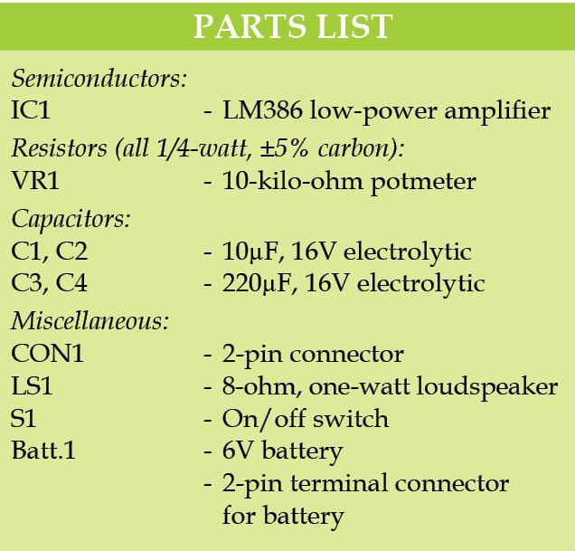
It is built around popular amplifier LM386 (IC1), an 8-ohm, one-watt speaker (LS1), four capacitors and a few other components. A 6V battery is used to power this project.
Four electrolytic capacitors [two 10µF, 16V (C1 and C2) and two 220µF, 16V (C3 and C4)] are used in this circuit. C1 is connected to the middle terminal of 10k potentiometer VR1.
C2 is connected to pins 1 and 8 of IC1. Pin 5 of IC1 is its output terminal, which is connected to speaker LS1 through C3.
C4 is connected to the positive terminal of 6V battery and ground. Positive side of 6V is connected to pin 6 of IC1 and the other side to ground terminal to pin 4.
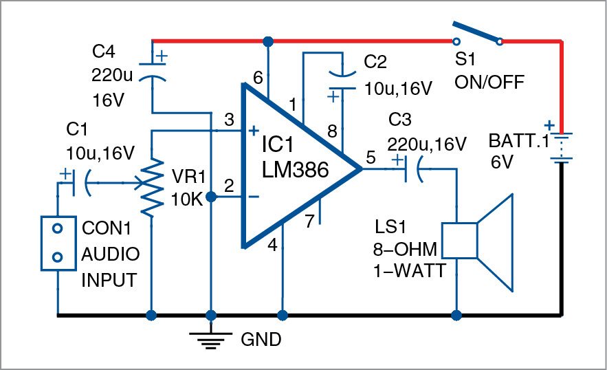
Inverting pin 2 of IC1 is connected to ground and non-inverting pin 3 is connected to the input terminal through VR1. Audio input is fed to CON1. VR1 is used to control volume.
Construction and Testing
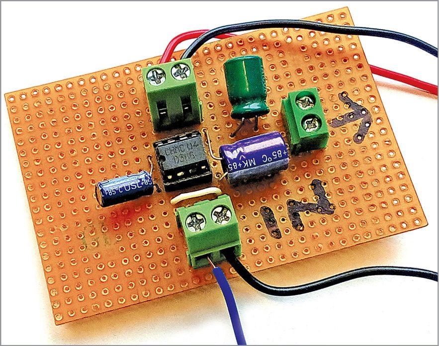
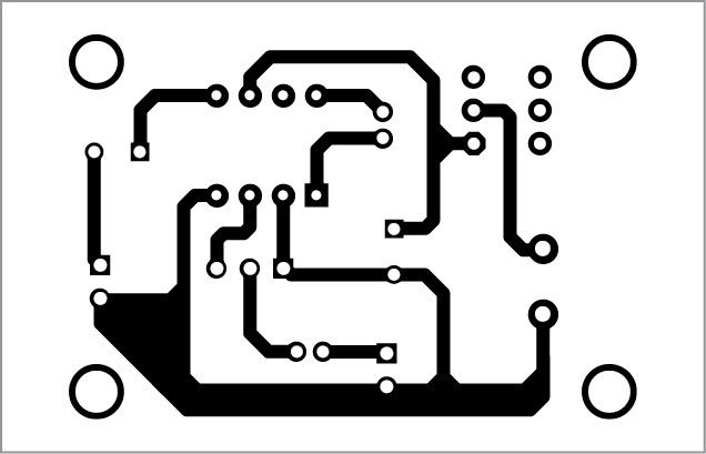
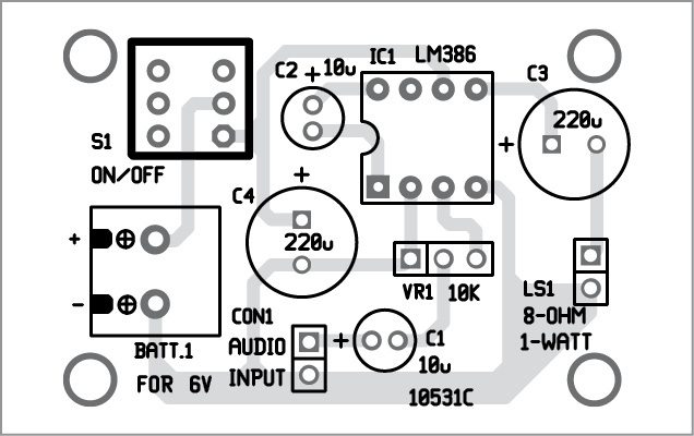
A single-side PCB for LM386 amplifier is shown in Fig. 4 and its component layout in Fig. 5. After assembling the circuit on a PCB, enclose it in a suitable box.
Fix connector CON1 on the front panel for input and loudspeaker LS1 at the rear side of the box. Connect VR1 on the front panel for controlling the volume.
Download PCB and component layout PDFs: click here
Before using this project, test it using the 6V battery. Connect the 8-ohm, one-watt speaker to output pin 5 of IC1 through C3. Switch on S1 and keep VR1 to its mid position.
Now, take a screwdriver and gently touch it on input terminal pin 3 of IC1. You should hear a humming sound from the speaker. This will confirm that your circuit is working and ready to use.
Note: LM386 provides an output of 250 milliwatts to one watt depending on supply voltage and load. Refer its datasheet for details.
We have also built Low-Cost Stereo Audio Amplifier Under 50 Rupees and Simple Audio Amplifier with Dual Power Source.
We’d love to hear about your experiences with this project! Leave a comment below with any questions, feedback, or improvements you’ve made.
Raj K. Gorkhali is a regular contributor to EFY. His interests include designing electronics circuits.
This article was first published on 28 February 2017 and was updated on 23 October 2025.
Hi, This looks like a nice wee project for my young secondary school students. It will be more convenient to have a 9v supply. Do you think this will require any other changes to be made? Regards, Chris
LM386 can work without any problem from 6 – 12 volt. (Refer datasheet). Only make sure the capacitors are of higher voltage (16 volt in the given circuit is fine).
You will get better sound and more volume with higher voltage
Is audio input work for microphone?
Hello sir i am your big fan i want make a 500 2att a best hometheate please suggest me
This IC is basically a power amplifier. It is not meant to be used with very high gain. So you can not directly use a microphone to drive this amp. Assuming a power output of 700 mW across 8 ohms, with a gain of 26 dB you need an input signal of roughly 120 mV. A dynamic microphone has an output of about 0.6mV to 1mV. assuming 1mV, you need a pre-amplification of about 100 or 40dB. This can be achieved by a simple two transistor pre-amplifier. Hope this helps.
Dear Chinmoy Mitra, a very nice suggestion for this Audio Amplifier. The IC itself, fondly called “The Workhorse IC” by hobbyists, will go on and on for a very long time. LM386N-4 can operate in up to 19VDC supply.Besides being an audio amplifier, this can also be used as Power Converters and DC Drivers. Thank you very much.
Sir I am very much interested in your LM 386 of audio board PCB with LM 386 IC removable mount.How much does the 150 nos of PCB ,s cost and where it is available in Hyderabad sir.
Kindly provide me the information.
Thank you.
hi sir
i have made this amplifier and it works very nice but the noise is too much, should i add more capacitors or replace the ones with higher values?
I already have these components, am going to make up as many as possible for crystal radio projects as well as regenerative shortwave radios. Thank you and hope to see more of these simple projects I have a article by Lance Borden of Borden Radio in the USA of almost the same lay-out.. But I like your layout much better especially the curcuit board version. Steven
Hi. Stephen, could you share a diagram of Lance Borden amplifier, I really need it! Thank you in advance.
Please recoment the aurdino using projects
Input to vr is pin no. 2
Is it right connection?
in the diagram correct…
but in pcb not correct
Please elaborate what is correct and what is wrong.
Generally we connect Input Wire to the Pin 1 of Volume Control counting from left to right.
It depends how you connect it. The given configuration also works perfectly
Hello Ray, I have one correction, C2 is connected faulty, the plus of C2 must be connected to pin 1 of the LM386.
regards, Roel
While polarities of C2 does not affect the performance here, you may interchange the polarities of C2 as per the manufacturer specifications, if required.
I tried and This not work, wasted time.
Kindly elaborate your query.
Do you have a. Agent in USA, or do you sell your magazine the US?
Why we use 6v battery.
Hi sir. I am restoring my 1970’s transistor radio MW/SW receiver. It has AC127 /128 complimentary pairs whereas AC127 has collector to emitter leakage so the hum is very audible. May I replace the entire output stage with LM386 for its 8ohm speaker. Also the unregulated dc voltage comes around 8 volts. Please suggest.
Circuit makes a lot of noise