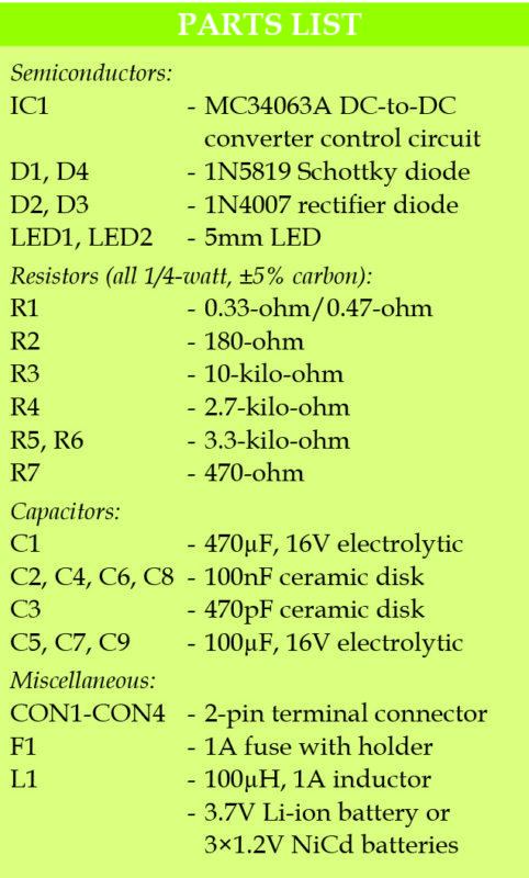
 This article presents a simple, low-cost DC to DC converter that converts 3.6V-3.7V battery input into three outputs of 6V, 5.3V and 5V. These voltage outputs can be used simultaneously or separately.
The converter is useful for digital and analogue audio equipment including portable audio amplifiers and MP3 players, and for experiments with digital and analogue electronics.
3.7V and 3.6V (3×1.2V) rechargeable batteries are widely available at low cost. But most equipment operates off 5V or 6V. So, you cannot use 3.7V and 3.6V batteries even if you use two 3.7V batteries (3.7×2=7.4V) or four 1.2V batteries (1.2×4=4.8V).
Hence you need a small DC-to-DC converter to get 5V, 6V or both of these, depending on the intended application. The converter described here provides a simple solution using an MC34063A IC.

Advantages of MC34063
MC34063A is ideal for small projects like DC-to-DC converters as it offers the following advantages:
1. Low cost
2. Easy-to-use DIP8 package
3. Operating input voltage of 3V-40V DC from NiCd, NiMH or Li-ion rechargeable batteries
4. Low quiescent current
5. Current limiting feature for the input voltage
6. Output adjustable with the help of a simple resistor divider network or trimmer potentiometer
7. Typical operation frequency of around 45kHz, which can be increased to around 100kHz
8. Built-in reference voltage of 1.25V
9. Internal output transistor capable of switching up to 1.5A
Circuit and Working
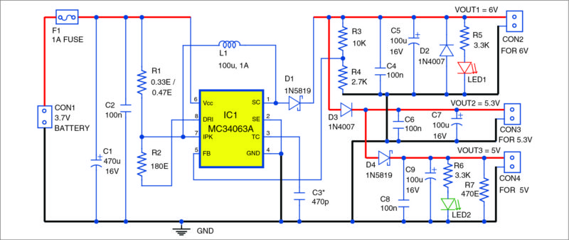
Fig. 1 shows circuit of the 3.7V to 5V-6V DC to DC converter. It is built around switching regulator MC34063A (IC1), two 1N5819 Schottky diodes (D1 and D4), two 1N4007 rectifier diodes (D2 and D3), two 5mm LEDs (LED1 and LED2) and a few other components.

Input DC voltage of 3.7V is applied to connector CON1. The circuit works with DC voltage in the range of 3.0V to 40.0V. IC1 works as a step-up converter to produce 6V output voltage (VOUT1), which is available at connector CON2. For Schottky diode D1, you can use any of 1N5817, 1N5818 and 1N5819 variants.
Diode D3 reduces the 6V output voltage to around 5.3V (VOUT2), which is available across connector CON3. Schottky diode D4 further reduces 5.3V to around 5.0V (VOUT3), which is available across connector CON4.
The total maximal output current from all outputs at CON2, CON3 and CON4 is around 100mA, which can be adjusted with the help of components in the circuit. The DC-to-DC converter also outputs around 15mV ripples, which can be reduced to some degree with the help of capacitor C3 and additional LC or RC filters.
Construction and Testing
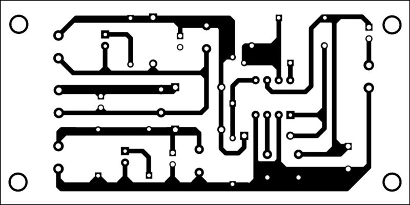
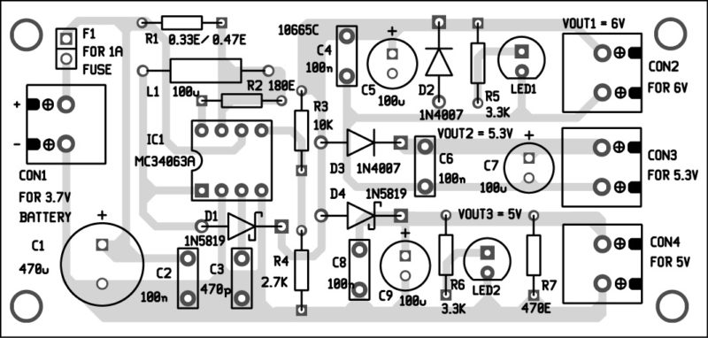
An actual-size PCB layout for the 3.7V to 5V and 6V DC-to-DC converter is shown in Fig. 2 and its components layout in Fig. 3. After assembling the circuit on the PCB, enclose it in a suitable box. Fix connector CON2 through CON4 and LED1 and LED2 on front side of the box.

The circuit does not need any adjustment. But you need to check input and output voltages, currents and frequency of operation of IC1. It is also good to control the current of inductor L1.

The circuit can be tested with a 3.7V Li-ion battery or with three 1.2V NiCd or NiMH batteries. You can also use any regulated power supply source producing 3.7V.
Note
1. The output voltage without load depends on the value of resistor R7 (between 270 and 470 ohms).
2. You should always have a load connected at CON4, at least 10mA, in order to allow normal operation of the circuit.
3. Current sensing mainly depends on resistor R1.
Download PCB and Component layout PDFs: click here
This article was originally published on 13th October 2017


looking for conversion /storage/inverter link – 6 dc to 6 av any product available interested to buy.
[email protected]
Would it be possible to simply remove the 5.3V and 5V part of the schematic? I only need the 6V output. Do you think the circuit still work?
Yes, it will definitely work even after removing the 5.3V and 5V parts of the circuit.