


 Microrobots with live audio and video streaming capabilities can help in tracking human beings during earthquakes and also perform underground surveys. This mini spy car can inspect very minute hole areas that are not accessible to humans.
Hence these microbots are essential to find people stuck under collapsed buildings due to earthquakes.
These small micro-size robots are equipped with a camera that helps in spying or helps the army and intelligence system in collecting information and live video footage and activity on the enemy and terrorists.

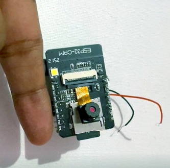
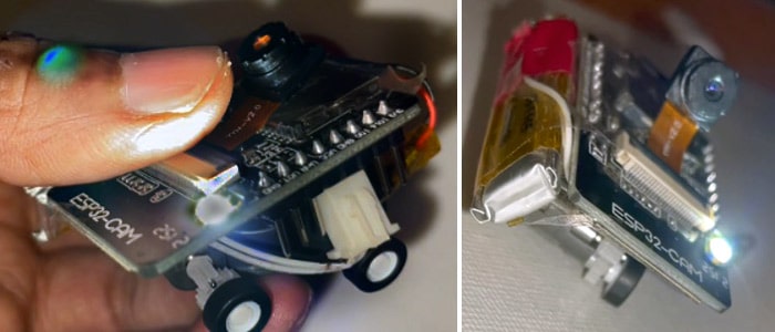
But designing such micro-sized SPY BOTs is very complicated. Hence the proposed design of micro-sized SPY BOTs size is not longer than a small finger and can go easily in minute holes to collect the data.
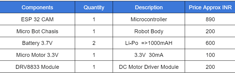
Below are the components required to design microsized SPY bots.
Bill of Material
Micro Spy Bot Code
Install ESP32 board onto Arduino IDE and then prepare a code to obtain live video from the camera wirelessly over Wi-Fi and also able to control the robot wirelessly.
First, open the preferences in Arduino IDE and paste the following link:
http://arduino.esp8266.com/stable/package_esp8266com_index.json, https://dl.espressif.com/dl/package_esp32_index.json.
Open the board manager and search the ESP32, and Install it. Prepare the code for the robot, then go to the board and select ESP32 cam as a board.
Now write the code to get the live stream of video over Wi-Fi and also get the UI on the web server to control the robot. Select examples and then open the ESP32 cam example code.
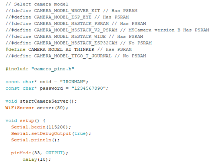
In the above example code, we can edit and make our code as follows:
First set the Wi-Fi SSID and password of the Wi-Fi network, it can be your phone hotspot, PC hotspot, or Wi-Fi router to which the robot is connected and can also control them.
Next, set the camera model names and pins of the camera that we have connected and used with our ESP32 board.
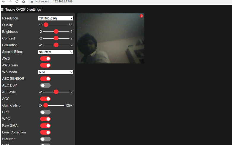
Now, the ESP32 board with an OV2640 camera is attached to the board and the board model name is the AI-Thinker board, so in the code select the “Camera Model AI Thinker board” and see the pins according to OV2640 pins.
Next, we set the pins for our robot control on the ESP board; we have 12, 13, 14, 15, and 16 pins free for basic i/O, hence, these pins can be used and set as an output in the setup function.
Set the ports 80 and 81 for the web server so with two web servers on the ESP32 board one on port 80 which is for getting the live video stream and control over Wi-Fi and the other on port 81 which is webpage UI to controls the robot forward and backward movement, hence, in the setup function we start both web server.
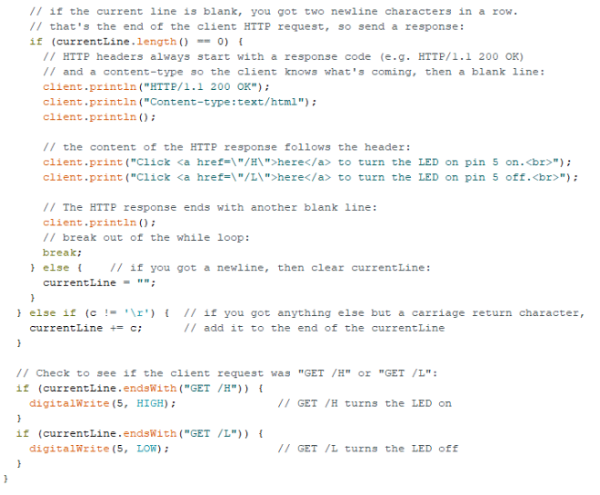
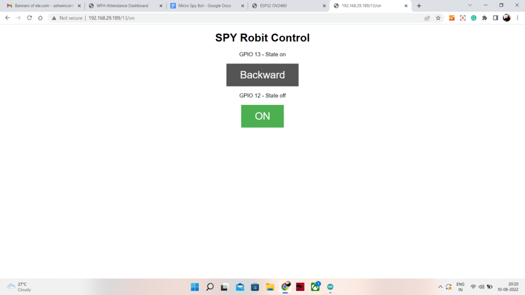
Next, we will create the loop function where we create the code for the UI of the robot controlling the web server and control the GPIO 12 and 13 to move the robot backward and forward.
We can use the motor driver with 4 inputs; for UI we create two buttons one is forward and one is backward and on each button pressed on UI, we will control two GPIO.
As if we click the forward button, then two GPIO 12 and 13 will set to output HIGH so robot move forward.
For backward, 14 and 15 GPIO is set to HIGH and previous 12 and 13 set to LOW to move spy car backward.
After completing the code, select the right part for ESP32 and then connect the ESP32 to the FTDO programmer and set the GPIO to GND for programming mode on the ESP32 cam, and then upload the code to the board.
Download Source Code
DIY Spy Car Circuit Connection
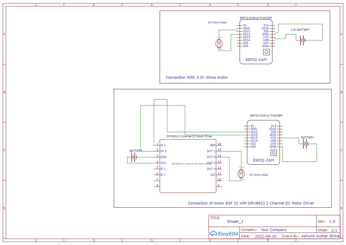
Now after uploading the code to the ESP32 board, connect the motor according to the circuit diagram. If your motor is using a current of more than 30mA, then you need to attach the motor driver as well, So follow the circuit diagram if you use the motor driver.
In my case, my motor directly runs on connection with GPIO without a motor driver so I have to use the GPIO and connect the motor directly to it but it’s dangerous and might burn your costly ESP32 cam board if our motor draws more than 40 mA current.
So you can take a risk and check or you can use the motor driver to drive the robot motor. Here we used the DRV8833 motor driver.
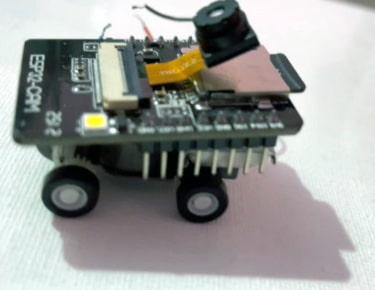
Now after connecting the components together, mount the motor on the microrobot chassis and then fix the battery for driving the motor in the robot.
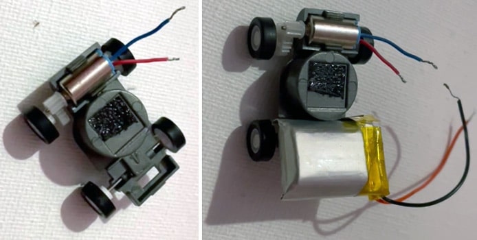
Then mount the ESP32 cam and fix it on that chassis. If you are using the motor driver then connect the motor driver below carefully with an extra insulation layer between the motor driver and ESP32 board so the components do not short each other.
Spy Car Testing
Now power the Robot with the battery we have attached earlier and then wait a few seconds to get the Robot connected to Wi-Fi.
Now in the web browser, open the IP address of the ESP32 cam, and now you can see the Live video footage.
To control the ROBOT, open the following URL where the first part contains the ESP32 IP address and then followed with a pin number and GPIO state.
Well as we are talking about the spy device, we have one more spy device. It is the smallest DIY FM Audio Bug Spy Device.
Moreover, if you face any issues while making this mini spy car, please ask in the comments below.
We need a full video of it , like how to make
Maing details are there in article . I you have doubt in making ask me here in comments section . We also take live session on how to make on Friday I will try to cove this project as well keep checking https://www.electronicsforu.com/efy-diy-training