 This article describes a low-cost sensitive midget vibration detector that can interface directly with any microcontroller. The entire circuit operates off a single 5 volt supply. Probably there is no need to explain where such detector would be useful. These could be vibration/motion sensors, impact sensors and other areas where motion and acceleration are involved.
Midget Vibration Detector Circuit
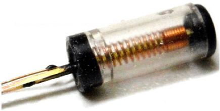
At the heart of the circuit is an inexpensive vibration sensor type SW18020P, made up of a small spring mechanism, which makes the contacts closed when the applied vibration force is at above a certain threshold. It has two terminals coming out of it. Normally the two terminal are insulated by a resistance value more than 10M Ohm. When someone applies vibratory force on the sensor, spring inside the sensor vibrates and makes a momentary short circuit (less than 5 Ohm) between the two contacts. When the force is removed the sensor contacts return back to the open state. Maximum working voltage (Vmax) of the sensor is 12V, and the maximum current (Imax) is 5mA. According to datasheet, the response time of the SW18020P sensor is about 2ms.

SW18020P – Internal View
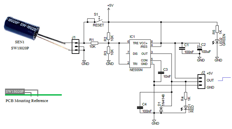
Rest of the circuit is centred around the venerable NE555N timer chip. Apart from the timing functions, the two comparators of the timer chip can be used independently for other applications. Here, the timer chip is configured as a simple bipolar latch switch with its two comparator inputs tied together and biased at ½ Vcc through a voltage divider. Since the threshold comparator will trip at 2/3 Vcc and the trigger comparator will trip at 1/3 Vcc, the bias provided by the resistors are centred within the comparators trip limits.
Circuit operation
In an idle state, output available from the circuit through the connector (J2) is at a logic-low (L) level. Incase of a valid vibration detection, this output goes to a logic-high (H) level – catering a dc voltage of around 3.6V – and remains in this active condition until cleared by the reset switch (S1). The green light (LED2) is the power indicator, and the red light (LED1) notifies the output status. Output of the circuit can directly be connected to the I/O port of a microcontroller in an existing security system for further processing, or it can be exploited to drive a low-current type (<100mA) electromagnetic relay without employing any additional hardware.

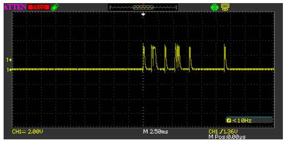
Also, you can see that vibration sensor output is an irregular pulse that rapidly decays. If you attach the vibration sensor directly to a microcontroller it might give undesired results, and/or upset the system. So, a signal conditioning trickery is used here to make this usable with digital electronics, too.
Construction
Even less-experienced hobbyists will find the assembly of the circuit on a general purpose printed circuit board a fairly easy affair since there is no complicated wiring and all components are housed on the board. As usual, mind the polarity of electrolytic capacitor and LEDs, and fit the IC in a suitable good quality socket, although this is not necessary. The vibration sensor element should be mounted at the top side of the circuit board (see the PCB mounting reference). The finished circuit may be fitted in any of a variety of small ABS cases. As the circuit has no adjustment points it is immediately ready for real-world applications.
Last word
Practically do not expect to do precise measurements with this midget vibration detector circuit. This resolution is good for detecting vibrations, shocks, and accelerations. If your application requires simple sensing this might be great choice and money saver.
Proof of Concept
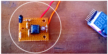
Author’s Prototype
Note that some components are soldered at the bottom side of the circuit board, and the power indicator not wired yet.


