

A 50kW power converter changes voltage levels and allows electricity to flow between the grid and energy storage systems in both directions.
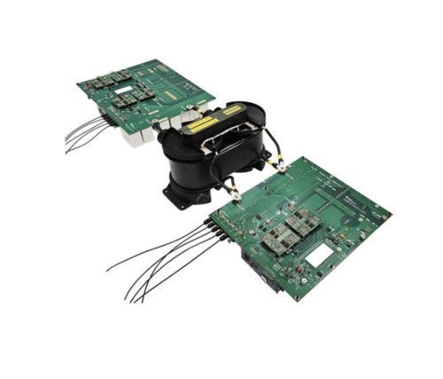
A 50kW solid-state transformer reference design from Texas Instruments (TI) uses silicon carbide (SiC) power devices and a modular converter architecture to convert power for medium-voltage applications, including renewable energy systems, battery energy storage and data centres.
The design uses a cascaded H-bridge (CHB) topology to distribute the input voltage across multiple converter submodules. Each submodule combines an H-bridge converter on the medium-voltage side with a dual active bridge (DAB) for isolated DC-to-DC conversion. The reference design supports bidirectional power flow, allowing energy to move between the grid and storage systems.
The medium-voltage direct current (DC) link is rated at 2.2kV, while the low-voltage DC link operates at 1.5kV. The design uses a three-phase architecture and has a rated power of 50kW.
Conventional transformers operate at the grid frequency of 50Hz or 60Hz and use iron cores. They can be bulky and heavy, particularly in installations that need to connect medium-voltage power to DC-based equipment. Solid-state transformers use high-frequency power conversion stages to perform voltage conversion and electrical isolation, potentially reducing transformer size and weight.
Medium-voltage grids typically operate between 10kV and 30kV. Standard power semiconductors cannot directly withstand these voltage levels in many converter configurations. The cascaded H-bridge approach addresses this challenge by dividing the voltage across series-connected converter cells. Each cell handles only a portion of the total voltage, allowing the use of commercially available SiC devices with lower voltage ratings.
The modular architecture also allows designers to adjust the number of submodules according to the required operating voltage. It can support redundancy, in which a faulty cell may be bypassed without shutting down the entire converter, depending on the system configuration.
The design uses SiC power devices to support switching at different frequencies across its conversion stages. The DC-to-AC stage operates at 10kHz in unipolar mode, while the DAB isolation stage switches at 100kHz. The higher switching frequency of the isolated DC-to-DC stage can reduce the size of its high-frequency magnetic components and help increase power density.
Fibre-optic links provide communication between submodules. These links support the electrical isolation required when control signals must pass between circuits operating at different medium-voltage potentials.
The design also supports bidirectional power transfer. This allows power to flow from the grid to a battery or other storage system and back towards the grid when required. Such operation is relevant to energy storage installations and power conversion systems that need to manage energy in both directions.
TI has tested this reference design. It comes with a bill of materials (BOM), schematics, assembly drawing, printed circuit board (PCB) layout, and more. The company’s website has additional data about the reference design. To read more about this reference design, click here.