


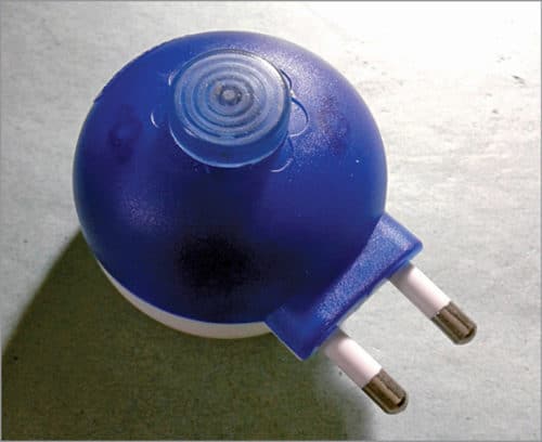
 This simple circuit can be used to light a small area at night. It is useful as a nifty bedroom night lamp, but it can also be used for other applications. The circuit is versatile and fully-automatic but draws very little electric current from the grid. Proposed enclosure of the project is shown in Fig. 1.
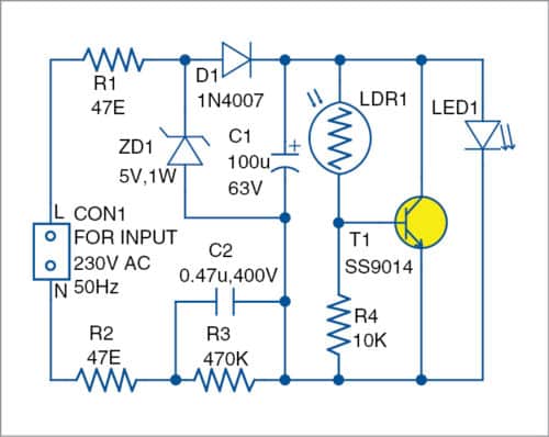
The circuit diagram of the nifty night lamp is shown in Fig. 2. It is built around two 47-ohm resistors (R1 and R2), rectifier diode 1N4007 (D1), 0.47µF, 400V capacitor (C2), transistor SS9014 (T1), LDR (LDR1), blue LED (LED1) and a few other components. CON1 is the input connector for 230V AC mains supply.
This lamp is designed for 230V AC mains transformer-less power supply. The components used here would help maintain overall efficiency and safety. The capacitive transformer-less power supply is a low-cost alternative to a traditional power supply.
The constant-current configuration used here provides about 30mA at 5V DC. Capacitor C2 is the key component here, while resistors R1 and R2 limit inrush current. Values of R1 and R2 are chosen such that these do not dissipate too much power yet are large enough to limit inrush current.
Resistor R3 (470-kilo-ohm) in parallel with C2 creates a filter that will attenuate EMI travelling back to the grid. It also works as a bleeder resistor to discharge the capacitor when disconnected from AC mains (wall plug).
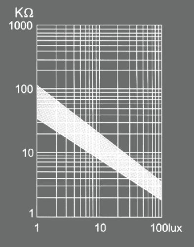
Light resistance of GL5528 LDR at 10 lux (at 25°C) is 8k to 20k, and it shoots up to one-mega-ohm at near 0 lux (see Fig. 3). So, when the night lamp is kept in the dark, T1 will be switched off and blue LED will glow. Note that the orthodox current-limiter resistor for LED is not used here.
As per calculations, power supply configuration will give a guaranteed output current close to 30mA at 5V, but exact output depends on tolerances of the components used.
Construction and testing
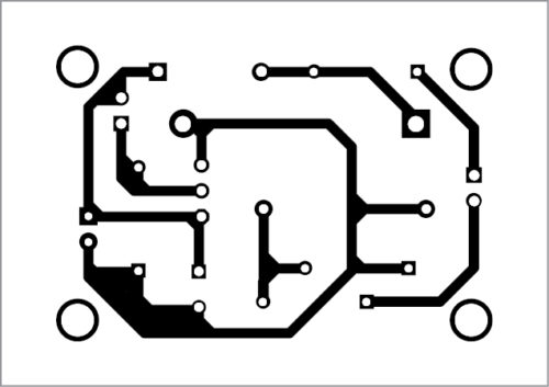
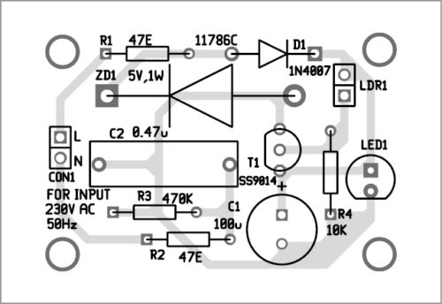
A PCB layout of the night lamp is shown in Fig. 4 and its components layout in Fig. 5. After assembling the circuit on the PCB, connect 230V AC mains across CON1.
Download PCB and component layout PDFs: click here
Since the circuit is simple, soldering and assembling is not too difficult. Even though the bill-of-material (BOM) includes leaded components to save space (height) and improve mechanical stability, it is preferable to use lead-less (SMD) components if you are an advanced solder artist.
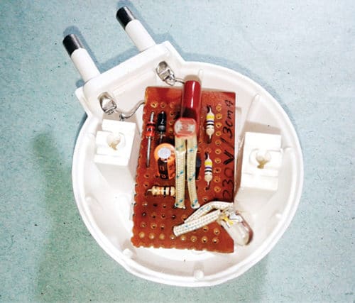
After assembling the components, enclose the circuit board in a suitable waterproof and flame-retardant box. The enclosure design depends on your artistic background and skill, which makes DIY construction an attractive experience. The author’s prototype wired on a perf board and enclosed in a defunct liquid vaporiser is shown in Fig. 6.
Note
Capacitive power supplies are not safe due to lack of isolation. But in sealed-off devices these can be a great way of getting the working voltage for certain applications. Obviously, such devices have power factor (PF) close to zero, making it questionable whether these meet the mandated PF laws.
Caution
There are chances of electric shock during experimentation with a transformer-less circuit interfaced to grid power. So, you must be very careful while handling this circuit.
T.K. Hareendran is an electronics hobbyist, freelance technical author and circuit designer. He is founder and promoter of TechNode

Forward drop of blue LED is about 3volt so entire 30ma will flow through led . whether blue LED is capable of withstand 30ma ?
I love your ingenuity! I was looking for ideas to add to my own nifty hobby projects for LEDs and bumped into yours. Mine are aimed at kids 12+ (and adults) so this one’s not for them 🙂