


 Presented here is an Arduino-based noise/sound level monitor that displays sound levels in decibels (dB) and corresponding voltage levels on an LCD. A noise monitoring system is used in many applications such as healthcare, defence, mining, robotics and so on.
This circuit is especially designed for noise monitoring in public places such as parties and marriage functions. The hearing capability of a person is around 80dB—sounds above this can cause hearing loss if high sound levels or volume are played for long.
Circuit and Working
The circuit diagram of the noise monitoring system is shown in Fig. 1. It is built around Arduino Uno board, 9V battery, 16×2 alphanumeric LCD (JHD162A), sound sensor module and a few other components.

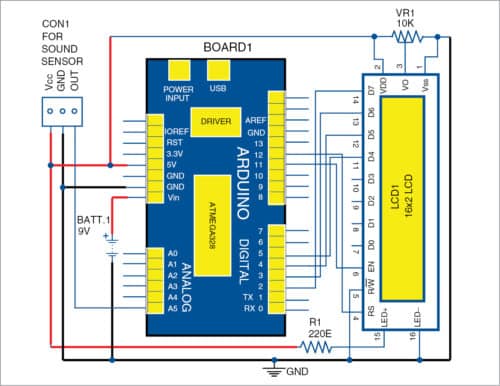
When sound is detected by the microphone in the sound sensor module, corresponding voltage and sound levels are displayed in dB on LCD1. Sound sensor output is analogue voltage, which gets converted to digital through the inbuilt analogue-to-digital converter of the Arduino. Analogue voltage ranges from 0V though 5V, and the corresponding equivalent digital value 0 through 1023 is displayed on the serial monitor of Arduino IDE.
Sound sensor module
This device receives sound waves and converts them into electrical signals. It detects the sound intensity in ambient atmosphere. The sound sensor module used in this project is shown in Fig. 2. It has a capacitive microphone that is sensitive to sound. Sound waves change capacitance and the corresponding voltage changes. Since change is quite weak, it needs to be amplified.
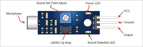
LM393 is used as a power amplifier in the module. It has a built-in preset to adjust sensitivity of the analogue output pin (OUT).
Connect OUT pin (or S pin in some cases) of the sound sensor module to analogue input pin of Arduino Uno. You will see the value of sound intensity on the serial monitor as well as on LCD1.
LCD module
16×2 LCD module (LCD1) is a 16-pin LCD, which is easily available in the market. Refer to its datasheet to get pin details. A preset (VR1) is used to adjust the contrast of the LCD display.
Arduino Uno
Arduino Uno R3 is based on ATmega328 microcontroller (MCU). It contains fourteen digital input/output pins, six analogue input pins, a 16MHz crystal oscillator, USB connection, power jack, ICSP header and reset button.
Programming is done using Arduino IDE. Analogue input pins A0 to A5 are available on Arduino Uno (Board1). When the software program (Audio_meter.ino) detects analogue signals on these input pins, corresponding signal is shown on the serial monitor of the PC and on LCD1.
Construction and testing
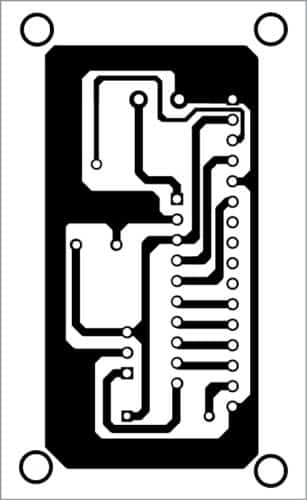
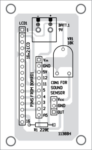
A PCB layout of the noise level monitor is shown in Fig. 3 and its components layout in Fig. 4. Assemble the components on the PCB as per the circuit diagram. In this project, analogue OUT pin of the sound sensor is connected to A5 pin of Arduino, Vcc pin to 5V and GND pin to ground pin (GND) of Arduino.
Download PCB and component layout PDFs: click here
Download Source Folder
Connect Arduino to a computer using a USB cable. Open the source code from Arduino IDE, select the proper COM port and board from Tools menu. After selecting the proper COM port and board, compile and upload the source code to the board.
After uploading the code, remove the USB cable and connect a 9V battery as power supply for standalone use. After 9V battery is connected to the circuit, you will see Audio Meter on LCD1. Now, speak in front of the microphone. The sound detected will be converted to corresponding analogue voltage, digital voltage and sound level in dB, and all these values will be displayed on LCD1. You can use this circuit to capture the noise around the meter.
The circuit has been tested for various situations and works fine.
Navpreet Singh Tung is an assistant professor and project coordinator in the department of electrical engineering at Bhutta Group of college, Punjab

Where can we use this in military applications…??
we can use to track the movement of objects related to wars like tank,robots,guns,men through audio as this gadget can detect even slight noise.
This was useful to me but i want project in hackathan.So please post or send related to this project sir.
The analog output of the sensor is the waveform, and does jot actually represent noise. This is an extremely inaccurate way of detecting noise and gives us no way to calibrate. Essentially this is a non-working circuit. Also the noise sensor mentioned has no model number or reference, but from experience it is low quality and only reacts to loud noises right next to the microphone, or extremely loud noises further away.