


 This project will enable remote control of two electrical appliances. It makes use of a TV or DVD remote that uses modulated infrared (IR) pulse train operating at 38kHz frequency.
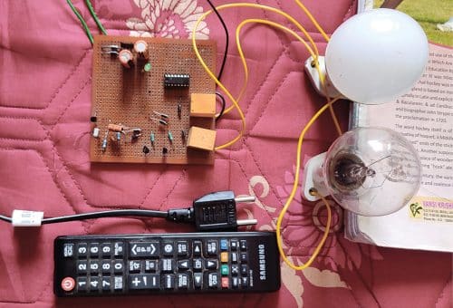
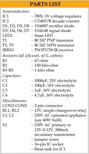
A good thing about this project is that it does not use any microcontroller and is based on a CD4017B decade counter IC and TSOP1738 IR receiver only to control two appliances. The author’s prototype is shown in Fig. 1.
Circuit and working
Circuit diagram of the two-channel IR remote control switch shown in Fig. 2 can be divided into two parts: regulated power supply and the control circuit.

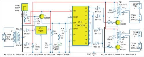
The regulated power supply is built around a 12V-0-12V, 500mA step-down centre-tapped transformer (X1), full-wave rectifier using 1N4007 diodes (D1 and D2), 5V regulator IC 7805 (IC1), and two electrolytic capacitors C1 and C2.
The control circuit is built around IC CD4017B (IC2), 1N4148 diodes (D3, D4, D6, and D7), transistor BC557 (T1), two BC547 transistors (T2 and T3), and two 12V relays (RL1 and RL2).
The project requires 5V for CD4017B IC and TSOP1738 IR receiver (IRRX1) and 12V unregulated DC for the two 12V single-changeover SPDT relays.
The TSOP1738 IR receiver at input side receives 38kHz IR pulses from the remote control. Under normal condition, the output pin of receiver is at logic high, which means transistor T1 is cut-off and its collector terminal is at logic low. The collector of T1 drives clock line of the CD4017B decade counter.
When you point a remote towards IR receiver and press any key, the circuit receives a train of 38kHz IR pulses. These pulses are inverted at the collector of T1 and given to the clock input of decade counter IC2.
The arriving pulses could increment the CD4017B counter at the same rate (38kHz) but, because of the RC filter circuit (comprising R2 and C3) at the clock input pin 14 of IC2, the train of pulses appear as a single pulse to the counter. Thus, on pressing each key, the CD4017B counter advances by a single count only.
When you release the remote’s key, capacitor C3 discharges through resistor R2 and the clock line becomes zero. So, every time you press and releases a key on the remote, CD4017B counter receives a single pulse at its clock input. LED1 glows to indicate that a pulse has been received by IC2 from the remote key.
There can be five cases (types) of operation:
Case 1
Initially, when you press a key on the IR remote, the O0 output of CD4017B goes high. The counter increments for each low-to-high going pulse arriving at its CLK pin (14). When the first pulse arrives, O0 goes high and transistor T2 conducts through diode D3. This activates relay RL1 and appliance L1 connected to it is turned on.
Case 2
When you press a key again, the second pulse arriving at CLK line increments the counter by one. So, O1 output of CD4017B goes high and transistor T3 conducts through diode D5. This activates relay RL2 and AC appliance L2 connected to it is turned on. At the same time, since output pin O0 is low, transistor T2 is cut-off by diode D3. This deactivates relay RL1 and appliance L1 is turned off.
Case 3
When you press a key once again, the third pulse arriving at CLK line again increments the counter by one. So, O2 output of CD4017B goes high and transistors T2 and T3 conduct through diodes D4 and D6, respectively. This activates both the relays (RL1 and RL2) and both the appliances (L1 and L2) are turned on.
Case 4
When you press a key for the fourth time, the fourth pulse arriving at CLK line increments the counter by one once more. So, O3 output of CD4017B goes high and output pins O0, O1, and O2 of CD4017B become low at the same time, which means transistors T2 and T3 are cut-off. This deactivates both the relays and both the appliances are turned off.
Case 5
If you press a key again, the fifth pulse arriving at CLK line again increments the counter by one. Since O4 is wired to the master reset pin 15 of IC2, it brings CD4017B back to the power-on-reset condition with O0 high.
The above cycle repeats whenever you press a key on the remote. Thus, the circuit simply operates as a two-channel on/off toggle switch for appliances, which is controlled using an IR remote device.
Construction and testing
A PCB layout for the two-channel IR remote control switch is shown in Fig. 3 and its components layout in Fig. 4. After assembling the circuit on PCB, connect the secondary of transformer across X1.
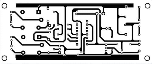
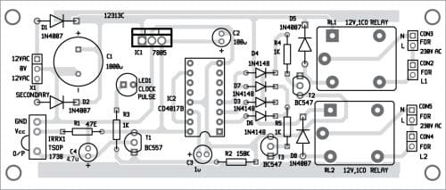
Download PCB and Component Layout PDFs: click here
In place of 230V AC operated appliances, you may use 60W, 230V AC bulbs for testing, as shown in the prototype (refer Fig. 1).
Pamarthi Kanakaraja is an assistant professor (R&D cell) at K.L. University, Vaddeswaram, Guntur district, Andhra Pradesh
