




Turn any toggle switch into a momentary push-button with one NE555 and a handful of common parts. Within just ‘2 hours’, you can build this ‘low’ complexity circuit for under ₹200!

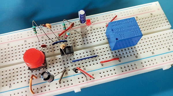
A toggle switch stays ON until you flip it back, but many systems expect a brief press, like a push-button. In a flight-simulator cockpit, for example, controls respond to keystrokes held for roughly 100-500 ms, and a toggle wired across the key lets the PC’s auto-repeat keep firing the function, which disrupts time-sensitive controls. This NE555 circuit solves that by converting a toggle switch’s change of state into a clean 1.1-second pulse, so a toggle can emulate a momentary push-button. An input from an external signal or toggle switch is turned into a sharp trigger by an AC-coupling and edge-detection stage, which triggers the NE555 one-shot to generate a single pulse of fixed duration. The output driver amplifies this pulse, and an indicator LED confirms it before it is delivered as a clean pulse output. Fig. 1 shows the author’s prototype.
What will you learn?
- How the NE555 timer can turn a simple toggle input into a useful momentary control pulse.
- How to detect a rising edge using an RC network and a diode.
- How to configure the NE555 in monostable mode.
- How to calculate and adjust the pulse width using the timing resistor and capacitor.
- How to drive a relay to control an external circuit with a short pulse.
- Why a flyback diode is needed to protect the circuit from the voltage spike a relay coil produces when switched off.
How it works
Fig. 2 shows the circuit diagram of the toggle-to-pulse switch converter. It is built around the popular NE555 timer IC and provides a simple, practical method for converting a toggle-switch input into a momentary pulse output. It generates a short, clean output pulse whenever a rising edge is detected at the input.

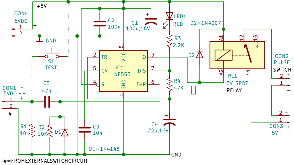
The 2-pin connector CON1 serves as the input terminal and accepts a 5V DC signal from an external toggle switch or other circuit. A push-to-on switch S1 is also provided for manual testing of the circuit.
Rising-edge detection is achieved through AC coupling using 47nF capacitor C5, which couples the input transition to the threshold pin6 of NE555 timer IC1. The threshold pin6 is normally held low by 10kΩ pull-down resistor R2, ensuring stable operation. A 1N4148 diode (D1) is connected across the input to suppress the response to the falling edge, allowing the circuit to respond primarily to the rising edge.

The RC network R4-C4 sets the pulse duration. When triggered, the NE555 generates a short pulse to energise relay RL1. To protect the circuit from back-EMF, a 1N4007 diode (D2) is wired across the relay coil, functioning as a freewheeling diode. A red LED (LED1) provides visual feedback, indicating the relay’s status during operation. Thus, each rising edge at CON1 converts the toggle-switch signal into a momentary relay action. CON2 provides an isolated pulse output for interfacing with other circuits or loads.
| Bill of Materials | ||||
| Reference | Component | Value/Type | Quantity | Cost (`) |
| IC2 | Timer IC | NE555 | 1 | 25 |
| D1 | Signal diode | 1N4148 | 1 | Miscellaneous ~175 |
| D2 | Rectifier diode | 1N4007 | 1 | |
| LED1 | LED | 5 mm, red | 1 | |
| R1, R2 | Resistor | 10kΩ, ¼ W, 5% | 2 | |
| R3 | Resistor | 2.2kΩ, ¼ W, 5% | 1 | |
| R4 | Resistor | 47kΩ, ¼ W, 5% | 1 | |
| C1 | Electrolytic capacitor | 100µF, 16 V | 1 | |
| C2 | Ceramic capacitor | 100nF | 1 | |
| C3 | Ceramic capacitor | 10nF | 1 | |
| C4 | Electrolytic capacitor | 22µF, 16 V | 1 | |
| C5 | Ceramic capacitor | 47nF | 1 | |
| RL1 | Relay | 5V SPDT | 1 | |
| S1 | Push-to-on switch | TEST | 1 | |
| CON1-CON4 | Connector | 2-pin | 4 | |
| – | General-purpose PCB or breadboard, jumper wires | – | As needed | |
| – | Power supply | 5V DC adaptor | 1 | Not included |
| Estimated total | 200 | |||
Construction
Assemble the circuit on a general-purpose PCB. To ensure stability and prevent erratic behavior, place the timing components R4 and C4 as close as possible to Pins 6 and 7 of the NE555; this minimises stray capacitance. For a cleaner layout, use solid-core hookup wire to make neat point-to-point connections on the underside of the PCB. Alternatively, the circuit can be quickly prototyped on a breadboard as shown in the author’s prototype (Fig. 1).
Testing
- Power up. Connect a regulated 5V DC power supply to the input terminal (CON4).
- Manual trigger. Momentarily press the TEST switch (S1). This action manually triggers the NE555 timer, which should instantly illuminate LED1 (Red).
- Relay verification. Listen closely for a distinct clicking sound from the RL1 (5V SPDT) relay, confirming that its internal switch contacts have successfully actuated.
- Timing check. After approximately 1.1 seconds, the timing cycle will complete. LED1 should turn off, and the relay should click a second time as it de-energises and drops back into its standby state.
Troubleshooting
If your circuit isn’t behaving as expected, use this systematic checklist to diagnose and resolve the issue:
1. Relay chatter or random triggering.
- Cause. Often triggered by 5V supply dips, ripples, or electrical noise.
- Fix. Ensure your power supply is clean and stable. Verify that proper decoupling capacitors are connected close to the IC pins.
2. Incorrect or unstable relay ON-time.
- Cause. Faulty, incorrectly rated, or loose connections in the R4/C4 timing network, or electrical noise affecting the control-voltage (Pin 5) pin.
- Fix. Re-check the values and soldering of R4 and C4. If the timing varies randomly, add a small ceramic capacitor (typically 0.01µF) from Pin 5 to ground to filter out noise.
3. Immediate NE555 IC failure.
- Cause. A missing, faulty, or backward-installed flyback diode (D2) across the relay coil. Without it, inductive voltage spikes from the coil can instantly destroy the IC.
- Fix. Ensure D2 (e.g., 1N4007) is correctly connected in reverse-bias directly across the relay coil terminals.
4. External trigger failure.
- Cause. Component faults or bad solder joints within the input network consisting of CON1, C5, R1, R2, or D1.
- Fix. Trace the trigger pulse at Pin 2 using an oscilloscope or multimeter. Remember that the NE555 triggers on a LOW pulse; ensure that Pin 2 rests HIGH and briefly drops LOW only when the external trigger is applied.
General circuit check
- Double-check all component values, structural orientations (especially polarised capacitors and diodes), and look for cold solder joints.
- Verify that your grounding is solid across the entire PCB layout.
Applications
Use this circuit for control panel applications, or to drive momentary-input devices such as power buttons, gate triggers, and latching relays.
T.K. Hareendran is an electronics designer, hardware beta tester, technical author, and product reviewer