 All residential and industrial units have energy meters that show energy consumed by the users. But the power (watts) is not shown by these meters, except by some new models.
During measurement, all energy meters flash an LED at a predetermined rate that is called impulse rate. The common flash rates are 6,400 impulses/kWh, 3,200 impulses/kWh, etc. By using the flash rate and some math, the power can also be calculated.
Presented here is a circuit to calculate the power consumed with the help of pulsing LED light of the energy meter and show it.
Circuit and working
The circuit diagram of the optical wattmeter is shown in Fig. 1. The circuit includes Arduino Nano board (Board1), 16×2 LCD display LCD1, NPN transistor BC547 (T1), and photo-transistor L14F1 (T2).
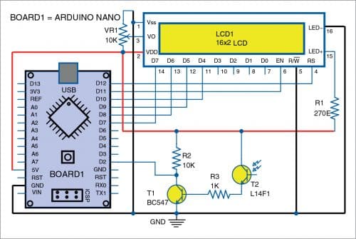
Whenever the energy meter’s LED light falls on photo-transistor T2, it conducts, thereby activating transistor T1. The pulse available at collector of T1 is given to first interrupt pin (pin D2) of the Arduino board. The Arduino calculates the power consumed in watts with the help of software, which is updated to the LCD display simultaneously.
[signinlocker id=”97843″]
Software
Arduino IDE is used to compile and upload program OpticalWattmeter.ino to the Arduino Nano board. Select the correct board from Board->Tools menu in Arduino IDE, select COM port and upload the program through the standard USB port in computer.
Note. There may be deviation in the wattage readings due to the use of millis library. If more accurate result is needed, use an ATmega328 chip with external crystal instead of resonator in the Arduino board and use the inbuilt hardware timer.
Download Source Code
Construction and testing
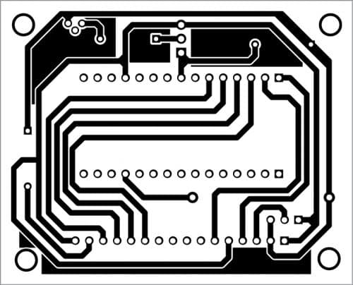
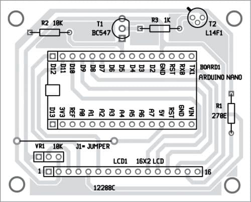
An actual-size PCB for optical wattmeter is shown in Fig. 2 and its component layout in Fig. 3. After assembling the circuit on PCB, enclose it in a suitable plastic box.
Download PCB and Component Layout PDFs: click here
Before mounting the Arduino on PCB, do not forget to upload the program on Arduino Nano board. Install photo-transistor L14F1 on the front panel such that it can capture the blinking LED light from energy meter.
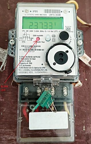
This circuit is developed for the energy meter having 6400 impulses/kWh. This can be changed in the program.
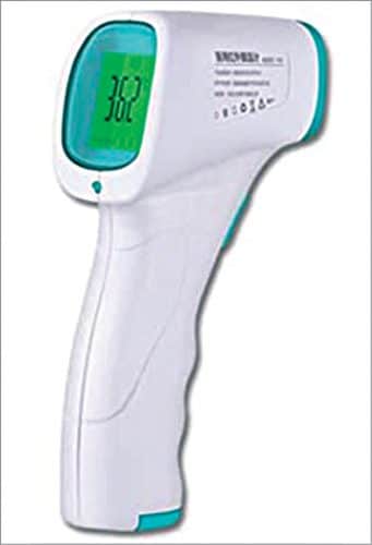
This circuit works on single phase supply only. Due to the low count of components, the circuit can be modified with a small OLED display and fitted into an enclosure like that of a non-contact thermometer (Fig. 5).
A. Samiuddhin, a circuit designer, is B.Tech in electrical and electronics engineering. His interests include LED lighting, power electronics, microcontrollers, and Arduino programming.
[/signinlocker]


