


 This password protected bluetooth based remote control operating at 2.4GHz frequency can be used to control robots, home appliances, machines, etc. Here we have used the secure remote to control a war robot that has three motors, one of which is used to lift objects or weapons such as a cutter (or sword). The article describes configuration of the remote control system and doesn’t cover construction and working of the robot in detail due to paucity of space.
Circuit and working
The project consists of two pairs of Arduino and Bluetooth HC-05 modules, one of which is used in the transmitter unit and the other in the receiver unit. The Bluetooth module on the transmitter side is configured as master, while the module on the receiver side is configured as slave. The author’s prototypes for the transmitter unit and the receiver unit are shown in Figs 1 and 2, respectively.
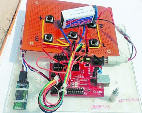

Fig. 1: Author’s prototype of transmitter unit
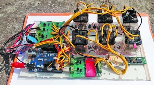

Fig. 2: Author’s prototype of receiver unit
Transmitter unit
Circuit diagram of the transmitter unit is shown in Fig. 3. The prototype uses six pushbuttons/switches (S1 through S6), which are connected to the Arduino board (Board1) using jumper wires. All these switches are used to control the motors for different movements of the robot. The HC-05 Bluetooth module (BT1) is also connected to Board1 as shown in Fig. 3.
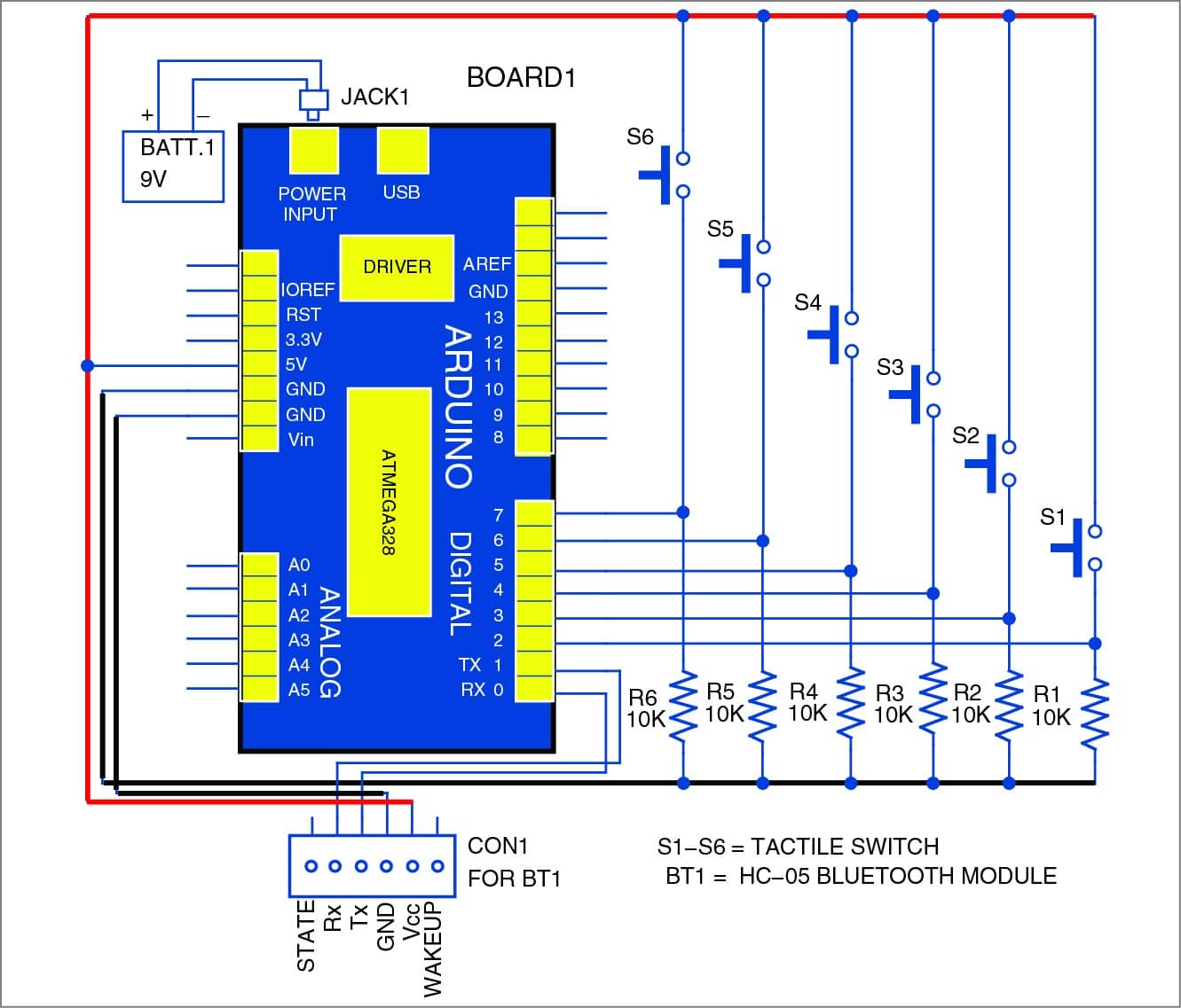
Fig. 3: Circuit diagram of transmitter unit
Receiver unit
Circuit diagram of the receiver unit is shown in Fig. 4. It consists of Arduino board (Board2), HC-05 Bluetooth module (BT2), six 12V, 1CO relays (RL1 through RL6), three DC motors (M1, M2 and M3), six relay driver transistors 2N2222 (T1 through T6) and a few other components. The author’s prototype uses a 4-channel relay card for the robot’s right and left wheels and a 2-channel relay card to drive the motor for lifting the object. BT2 is connected to Board2 using jumper wires. All the relay cards are connected to Board2.
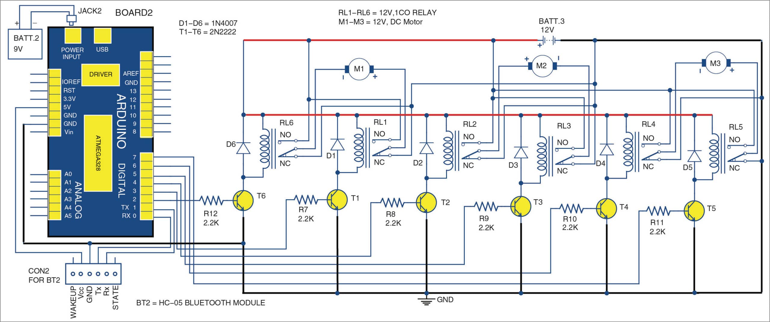
Fig. 4: Circuit diagram of receiver unit
The relay card should be made as per your requirement. In this tutorial, circuit is used to drive a robot using DC motors. So two relays are used to run a motor in both directions.
Switches S1 through S6 in the transmitter unit work as the remote control buttons, which send digital signals to the receiver unit through Board1 and BT1.
The signals from the transmitter unit are received by BT2 in the receiver unit and forwarded to Board2 for processing. Since relay boards are connected to digital output pins of Board2, the relay energises or de-energises as per the status of signals available on digital output pins.
Relays
Relays at the receiver side are used to drive the motors in the desired directions through Arduino Board2. Relay drivers include the combination of a transistor and a diode as shown in Fig. 4. You can use higher-power-rating relays for driving heavy DC motors. In the prototype, the author has used 12V DC, 8-pin JQX-30F power relays by removing sugar-cube PCB relays from the relay cards. Proper combination of relays and contacts makes the motors run in the desired directions.
Pairing of Bluetooth modules
HC-05 modules of the transmitter and the receiver are to be paired first before using them in the project. The process to configure the HC-05 modules is explained below.
To pair two HC-05 modules, you need an Arduino board and a USB-to-UART adaptor like CP2102 converter. An HC-05 module can be configured to work either in slave or master mode.
Configuring slave module. Connections between HC-05 and Arduino are shown below:
| HC-05 (BT2) | Arduino (Board 2) |
| Rx | Rx |
| Tx | Tx |
| GND | GND |
| Vcc | Vcc |
| Key | 3.3V |
In order to enter ‘attention’ (AT) command mode of HC-05, a null program is required in the Arduino board. (AT commands are Hayes command set commonly used in modem and serial communications.) The key pin of HC-05 must be connected to 3.3V in order to enter AT command mode.
After proper connections, check the baud rate of your HC-05 module. Configure the baud rate to 38400. Upload the following null program to Arduino board:
void setup()
{
}
void loop()
{
}
After uploading the program, start ‘Serial Monitor’ in Arduino IDE. Select ‘Both NL & CR’ and ‘Baud rate as 38400’ in ‘Serial Monitor’ window.
To know details of the current HC-05 device, just type AT+NAME in the edit box in ‘Serial Monitor.’ To change the device to the desired name, say, Tej Patel, type AT+NAME= Tej Patel
To change password of the module, enter the following command:
At+PSWD=*****
where ***** can be any character string, say, efy12
To configure the module in slave mode, type AT+ROLE=0
Every Bluetooth module has its own address. To know the current device address, type AT+ADDR
Here, the address is 98d3:31:305f7b
Replace colons with commas as given below:
AT+LINK=98d3,31,305f7b
And note down this address because you will need this later on while configuring the master module (BT1). Now, you may disconnect the power and remove the key pin from the module.
Power the module again. Slave module (BT2) is ready to use now.
Configuring master module
For this, you need a CP2102 converter (USB-to-UART) and also a terminal software. The author used a Tera Term software, which can be downloaded freely and easily from the Internet.
You need the following wiring connections between HC-05 module and CP2102 converter:
| HC-05 (BT1) | CP2102 |
| Vcc | +5V |
| GND | GND |
| Tx | Rx |
| Rx | Tx |
| Key | 3.3V |
After the connection, plug-in CP2102 module to USB port of your PC. Open Tera Term software from your PC and proceed as follows:
Step 1
Select ‘Serial’ option, followed by the COM port on which the CP2102 converter is connected
Step 2
Select Setup->Serial Port->Baudrate->38400
The default baud rate for HC-05 is 38400 for command mode
Step 3
Under the setup menu, select terminal as ‘CR+LF’ for Transmit. Also tick the local echo. Thus you can see whatever you have typed or entered in the window
Step 4
Type ‘AT+RMAAD’ to remove all the previously connected devices.
Set the password same as for slave by typing the following commands in the edit window of Tera Term:
AT+PSWD=*****
AT+ROLE=1. Here ‘1’ is for master mode
AT+CMODE=1 allows the module to connect to any address
AT+INIT. Type this command to initiate serial port. If you find error 17, don’t worry, it means you have already started SPP
AT+INQ. Type this to find devices near master module. After a while, you will get a list of the devices. To pair with the slave module, type:
AT+LINK=“the address with commas”
Here, AT+LINK=98d3,31,305f7b
Master module (BT1) is configured now.
Switch on both the BT1 and BT2 modules and see the status LEDs on both slave and master modules. Both modules should automatically connect to each other. If both LEDs start blinking twice in a second simultaneously, both devices are connected to each other and will remember each other even after their power is turned off.
Now the setup is complete and the wireless remote is ready to use.
Software program
Three programs (HC-05_config.slave.ino, TX-rem-cont.ino and RX-rem-cont.ino) are used in this project.
HC-05_config.slave.ino is used to configure Bluetooth slave module, TX-rem-cont.ino is used for transmitter Arduino and RX-rem-cont.ino is used for receiver Arduino.
You need Arduino IDE software to compile and upload these codes into their respective Arduino boards.
Main functions of Arduino codes are explained below:
pinMode( )
Configures the specified pin to behave either as an input or an output. See digital pin descriptions for detailed pin functionalities.
digitalWrite( )
If the pin is configured as an OUTPUT with pinMode( ), its voltage will be set to the corresponding value: 5V (or 3.3V on 3.3V boards) for HIGH, 0V (ground) for LOW.
digitalRead( )
Reads the value from a specified digital pin, either HIGH or LOW.
available( )
Gets the number of bytes (characters) available for reading from the serial port. This is the data that has already arrived and is stored in the serial receive buffer (which holds 64 bytes). available() inherits from the Stream utility class.
begin( )
Sets the data rate in bits per second (baud) for serial data transmission. For communicating with the computer, use one of these rates: 300, 600, 1200, 2400, 4800, 9600, 14400, 19200, 28800, 38400, 57600 or 115200. You can, however, specify other rates. For example, to communicate over digital pins 0 and 1 of Arduino that requires a particular baud rate.
println( )
Prints data to the serial port as human-readable ASCII text followed by a carriage return character.
Download source code
Construction and testing
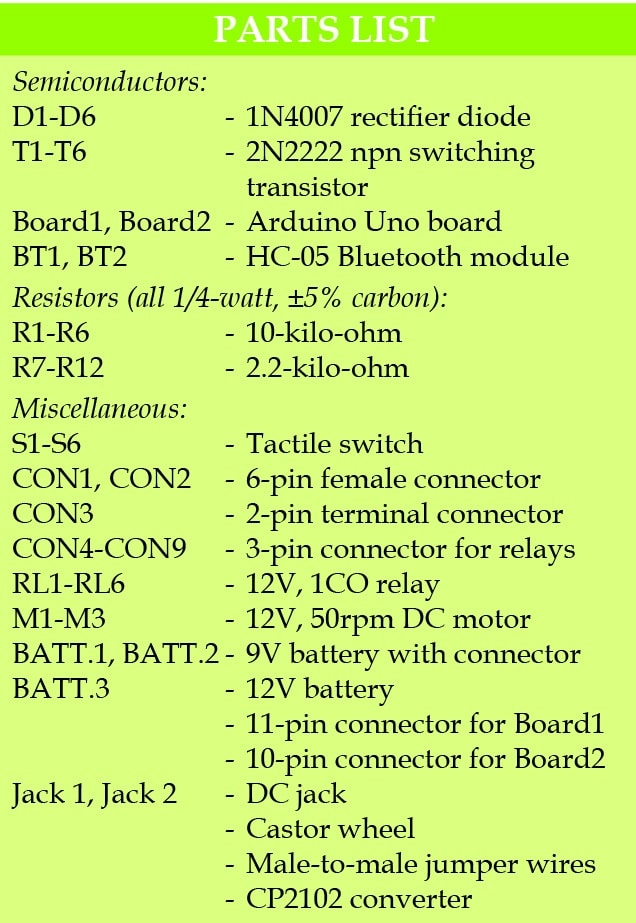
A PCB layout of the transmitter unit is shown in Fig. 5 and its components layout in Fig. 6. Similarly, PCB layout of the receiver unit is shown in Fig. 7 and its components layout in Fig. 8.
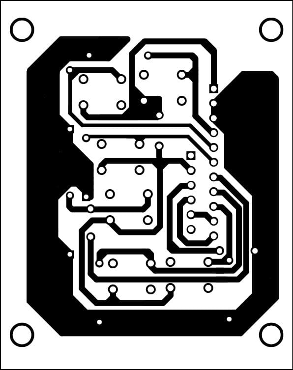
Fig. 5: PCB layout of transmitter unit
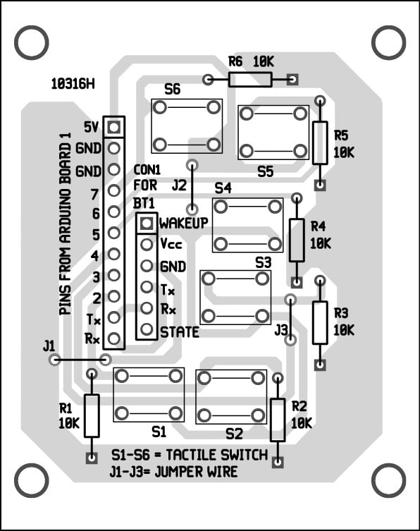
Fig. 7: Components layout for the PCB in Fig 5
Fig. 7: PCB layout of receiver unit
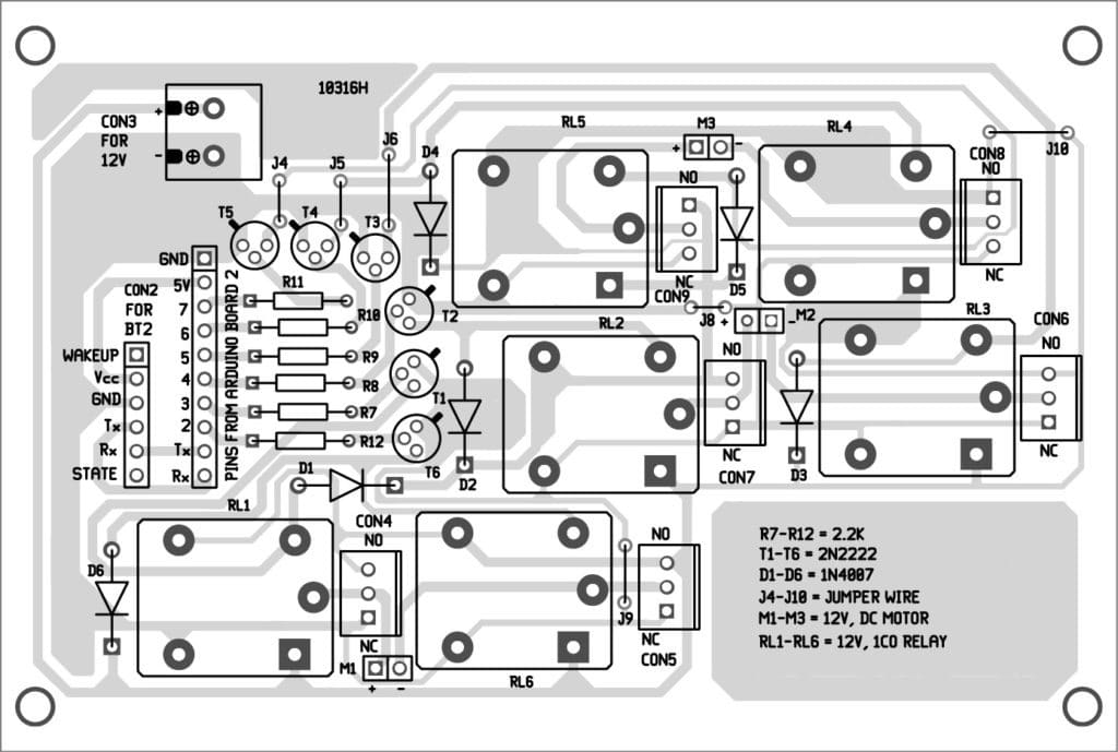
Fig. 8: Components layout for the PCB in Fig. 7
Download PCB and component layout PDFs: click here
Use two 50rpm DC motors for the wheels of the robot, one for right wheel and the other for left wheel. A castor wheel can be used as front wheel of the robot. Use another 50rpm DC motor for the object-lifting arm.
Connect 9V battery to both transmitter and receiver units. Connect 12V battery for the DC motors in the receiver unit.
Switch on both the transmitter and receiver units. If status LEDs of both BT1 and BT2 start blinking twice every second simultaneously, that means both devices are connected to each other. Now you can press any switch on the transmitter unit to control the robot. Switch S6 is used for lifting or cutting the object. Switches S1 through S5 are used for various movements of the robot.

