


 All schools and colleges follow a timetable for their classes, providing different time slots for different subjects. In order to follow the planned timetable, a person is assigned the job of turning on and off an electric bell manually at certain time intervals. Here we describe an automatic bell system that eliminates the need for human intervention. It is designed using simple digital electronics and is easy to construct. For clock and digital timer programming, a programmable time switch (Frontier TM-619) is used.
Circuit and working of Programmable Automatic Bell System
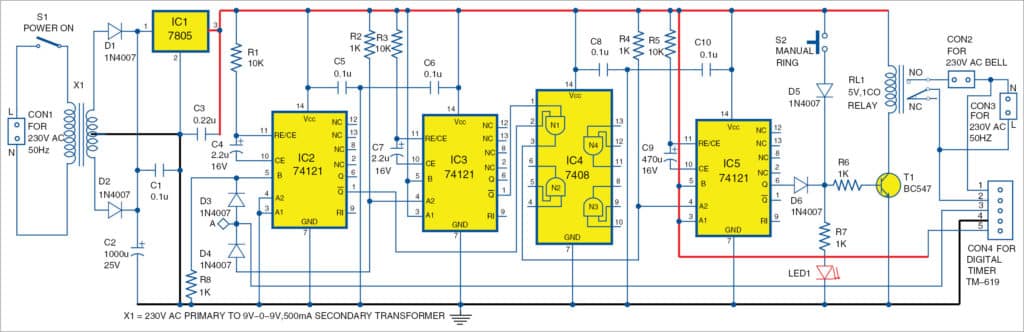
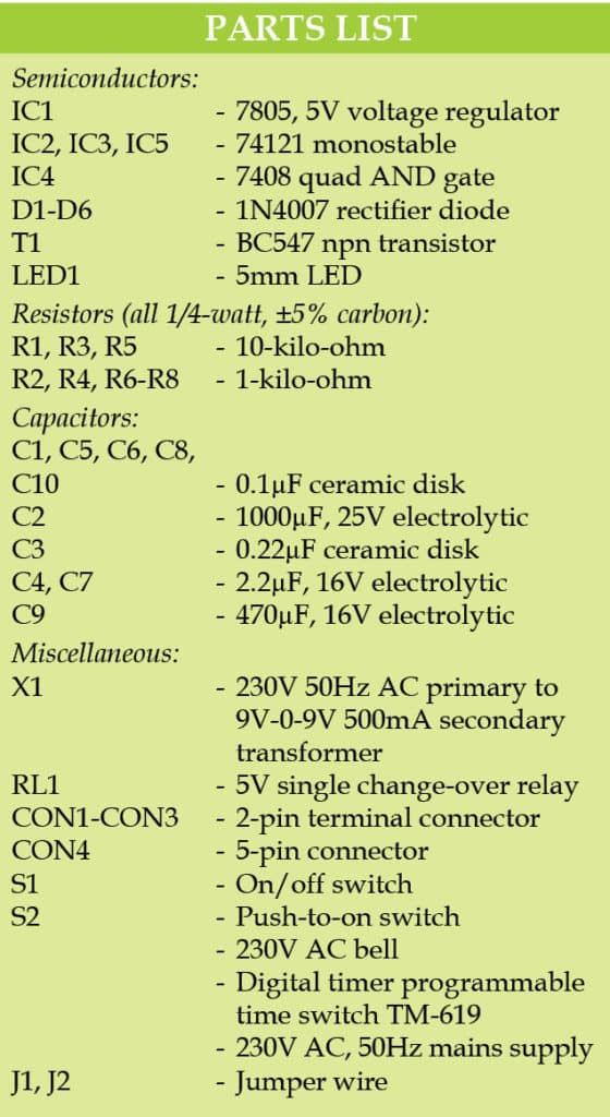
Circuit diagram of the programmable automatic bell system is shown in Fig. 1. It is built around a step-down transformer (X1), 5V voltage regulator IC 7805 (IC1), three 74121 monostable ICs (IC2, IC3 and IC5), quad AND gate IC 7408 (IC4), six 1N4007 diodes (D1 through D6), 230V AC bell, digital timer programmable time switch (TM-619) and a few other components.
The working of the circuit can be understood easily by referring to the truth table of IC 74121. Truth table is given in the datasheet, which is easily available on the Internet.

Fig. 1 shows how to use inputs of IC2 and IC3 for the required modes of operation, that is, falling-edge-triggered or rising-edge-triggered monostable multivibrator. Here, we use input A2 for falling-edge trigger of IC3, and input B for rising-edge trigger of IC2.
When we use input B for rising-edge trigger, A1, A2 or both these inputs of IC2 should be low, that is, connected to ground. Here, for convenience, both A1 and A2 are connected to ground. Similarly, for use of A2 as falling-edge trigger of IC3, pins A1 and B of IC3 should be high, that is, connected to 5V. Here IC2 is used as rising-edge-triggered, one-shot monostable multivibrator, whose time period is determined by the combination of resistor R1 and capacitor C4 as follows:
t= 0.69RC.
Here, value of R1 is taken as 10-kilo-ohm and C4 as 2.2µF for a pulse width of 1.5 milliseconds. Similarly, IC3 is used as a falling-edge-triggered one-shot monostable multivibrator, whose time period is determined by the combination of resistor R3 and capacitor C7. Here again, resistor and capacitor values are chosen for pulse duration of 1.5 milliseconds.
Q output of IC2 and IC3 are connected to input pins 2 and 1 of IC4, respectively. In normal condition, when there is no trigger to IC2 and IC3, Q outputs at pin 1 of both IC2 and IC3 are high. Therefore output pin 3 of IC4 (AND gate N1) is high, which is connected to trigger input A2 of IC5. Here IC5 is used as a falling-edge-triggered one-shot monostable multivibrator for pulse width of 3.2 seconds by choosing the values of resistor R5 and capacitor C9 as 10-kilo-ohm and 470µF, respectively. These values are selected depending on the time duration for which the bell should ring. You can use a potentiometer in place of the fixed-value R5 to vary the time duration as per the time slot of each class.
Normally, when Q output of IC2 and IC3 are high, N1 gate output of IC4 is also high. In this situation, Q output (pin 6) of IC5 is low. As transistor T1 is non-conducting, relay RL1 does not energise and the bell connected across CON2 remains off. The bell rings when Q output of IC5 goes high for predetermined time duration of 3.2 seconds. LED1 glows during this time duration.
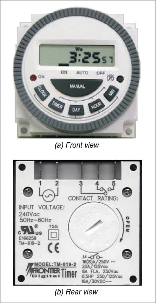
For programming digital timer switch TM-619, refer its user manual on the Internet . Working of the circuit with timer switch TM-619 is given below:
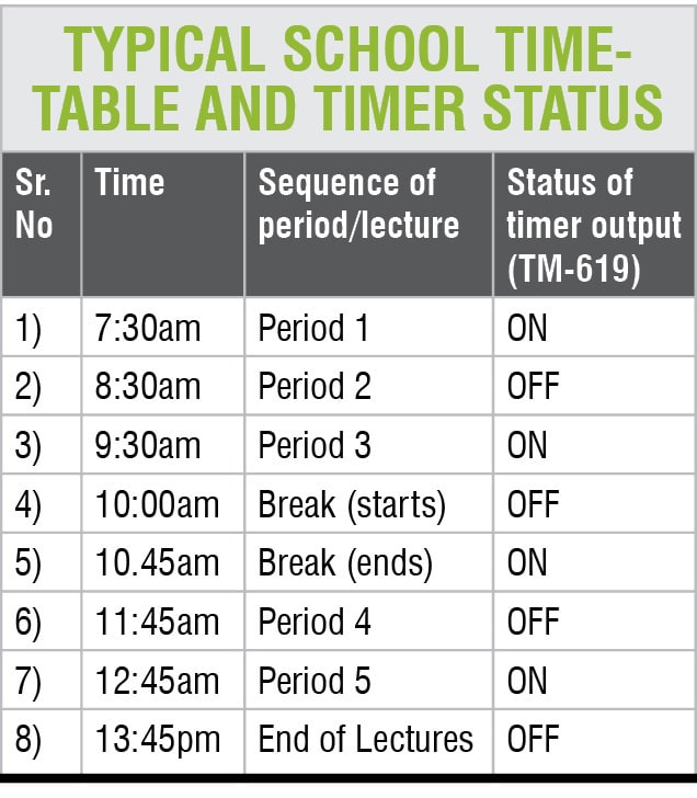
1. Program the digital timer switch (TM-619) as per the required timetable. As an example, typical timetable of a college/school is shown in the table. Note that at the end time of the lecture, the timer should be in ‘off’ condition as shown in the table. If the sequence ends with ‘on’ time, put an additional ‘off’ time by adding 5-minute time interval. This ensures that timer TM-619 output is in off condition so that it begins the next cycle with ‘on’ condition. Note that whenever the timer output toggles between ‘on’ and ‘off’ conditions, output pin 6 of IC5 goes high for 3.2 seconds. This means, the AC bell rings for 3.2 seconds.
2. After programming, put the timer in auto mode.
3. When the timer clock reaches preset time, its status changes from ‘on’ to ‘off’ and vice versa.
4. Accordingly, the timer clock generates a falling-edge or rising-edge trigger signal for monostable IC2 and IC3. Q output of the respective IC generates a low-going pulse with pulse width of 1.5 milliseconds, which, in turn, triggers IC5. Transistor T1 conducts to energise relay RL1 and the bell rings for 3.2 seconds.
5. The process repeats as per the timetable.
Construction and testing
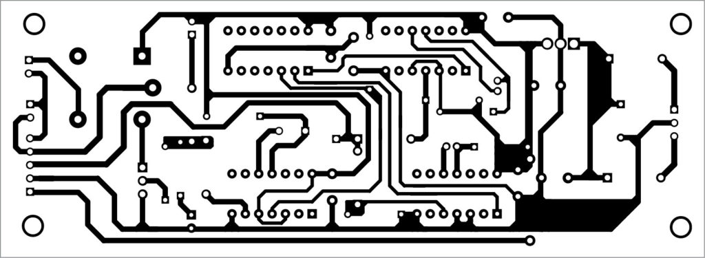
An actual-size PCB layout of the programmable automatic bell system is shown in Fig. 3 and its components layout in Fig. 4.

Download PCB and component layout PDFs: click here
Download source code
After mounting components on the PCB, first check Q output of IC2 using an oscilloscope; when a positive trigger is given to pin 5 (input B), the pulse width at pin 1 should be 1.5 milliseconds. Similarly, check pulse output pin 1 (Q) of IC3 by giving a negative trigger to pin 4 (A2 input) of IC3.
The output of IC5 drives the base of npn transistor T1 (BC 547) through diode D6 and resistor R6.
In order to test the bell manually, a push-to-on switch (S2) is provided. It is connected to the base of the transistor through diode D5. When you press S2, transistor T1 conducts to drive relay RL1 and the bell rings continuously as long as S2 is pressed.
In normal condition, transistor T1 gets the pulse from pin 6 of IC5. As it has pulse width of 3.2 seconds, the bell rings only for 3.2 seconds.
After assembling the circuit on the PCB, connect 230V AC to CON1. Also connect the digital timer and 230V AC bell externally to the PCB using external wires. Connect switches S1 and S2, and LED1, on the front panel of the cabinet. Note that the PCB shows only the secondary winding of X1 (9V-0-9V). Affix the switch S1 on the cabinet at a suitable location and connect to primary winding of X1 using external wires.
Dr S.B. Iyyer is head of the department of physics, Ahmednagar College, Ahmednagar
Rahul Sathe is research project fellow, Ahmednagar College, Ahmednagar
why should we use in 3 monostable multivibrator
which block is memory unit in this circuit
How can I modify the bell above to design a programmable soltric bell?