


 When the author decided to develop a magnet operated toggle switch, what he had had in mind was an ‘unorthodox’ design that was as simple and sensitive as possible. Admit it, here is a better and more convenient solution without employing any traditional ICs usually used by almost all circuit designers!
Magnet operated toggle switch circuit
As can be witnessed from the schematic drawing this no-frills toggle switch circuit does indeed contain very few components. The circuit uses an integrated Hall sensor ATS276 fitted in the master unit (as magnet sensor), sensitive enough to detect magnetic proximity at a distance of a few centimeters from the active area (marking side) of the sensor element. In operation the circuit consumes around 50 mA, so a 12 V stabilized mains adapter is an ideal power source, but batteries could also be used and would give a reasonable life expectancy if the unit was not in continuous operation.
ATS276 is an integrated hall sensor with output drivers, primarily designed for electronic commutation of brush-less dc (BLDC) Fan. This sensor internally includes the power supply regulator, protecting diode, hall plate, amplifier, comparator and a pair of complementary open-collector outputs (DO, DOB). While the magnetic flux density (B) is larger than operate point (Bop), DO will turn on (low), and meanwhile DOB will turn off (high). Each output is latched until the magnetic flux (B) is lower than release point (Brp), and then DO, DOB transfer each state.
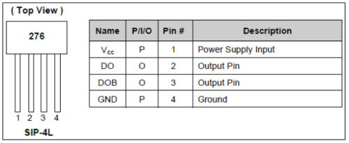
Pin assignments & pin descriptions of ATS 276
In addition to the Hall sensor chip (HS1), only an electromagnetic relay (RL1) and a status indicator (LED1) – of course with its current limiting resistor (R1) – is used here!
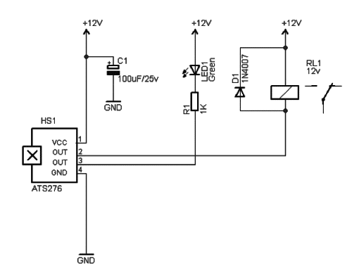
Magnet Operated Toggle Switch: Schematic Drawing
Construction & testing
The whole circuit can be fabricated on a little piece of perfboard. While mounting the Hall sensor, ensure that its active area (marking side) faces towards outside. During initial power-up, the relay activates and remains in the energized state. Bringing one pole of a neodymium magnet in proximity of the Hall sensor latches the circuit in reverse state (this condition is indicated by the status indicator), and bringing the other pole of the magnet in proximity of the Hall sensor, toggles the electromagnetic relay again. That’s all!
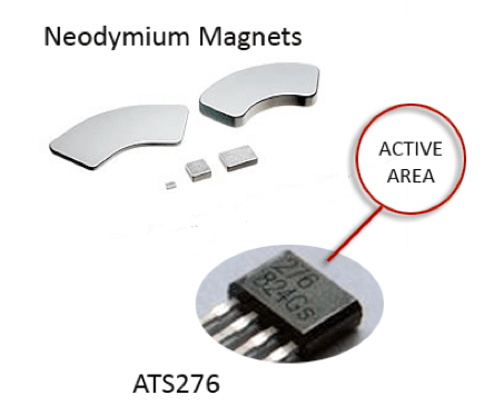
Neodymium magnets & active area of the hall sensor
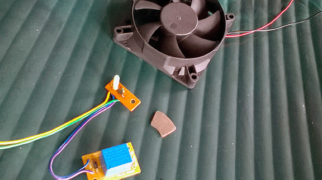
Author’s experimental setup
Test setup
Prototype was tested with ATS276 lifted from a 2-wire brushless dc cooling fan
Neodymium magnet used at that time was from an old hard disc drive