An RGB Bulb is readily available in the market but is highly expensive and based on a microcontroller.
Also, their programming is very difficult to understand. Here is a simple and cheap circuit for an RGB Bulb using NE555 Timer that you can build easily.
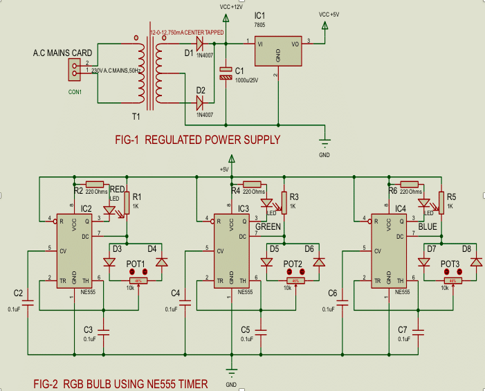
The main objective of this project is to produce different colors for party & functions with the help of NE555 timer IC. Here, I design a full wave rectifier mains supply, which is stepped down by transformer X1, rectified by a full-wave rectifier comprising diodes D1 and D2, (1N4007) filtered by capacitor C1 and fed to the regulator 7805 IC1 to maintain constant DC +5V at the output the constant output is fed to the circuit.

RGB bulb circuit
This project is developed in two parts, one is power supply (+5V) section FWR (Full Wave Rectifier) as a regulated power supply as shown in fig1, and another is the circuit diagram RGB Bulb using NE555 Timer as show below. The circuit is built around transformer (T1) 12-0-12, 750m Amp, rectifier diodes (D1, D2) 1N4007, filter 1000uf/25v, 7805 voltage regulator (IC1), NE555 Timer, three primary color LED’s they are Red, Green & Blue (8mm) along with some descriptive components.
As shown in figure 2, there are three astable multivibrators built using three NE555 each one for one LED – Red, Green and Blue. In each astable multivibrator block there is one 1 KΩ resistor, one 10 KΩ pot, 2 diodes 1n4007 and a 0.1uF capacitor connected for RC timing components.
- Vcc supply is given to pin 8 and pin 1 is connected to ground. This will provide biasing to NE555
- RESET input pin 4 is also connected to 5 V to enable output
- Control Voltage input pin 5 is connected to ground through 0.1uF capacitor
- 1 KΩ resistor is connected between Vcc and discharge input pin 7
- Two diodes (1N4007) are connected back to back with pin 7 and two fixed terminals of 10 KΩ pot to maintain 50% duty cycle.
- Third slider terminal of pot is connected to 0.1uF capacitor and threshold input pin 6
- Trigger input pin 2 is shorted with pin 6 to make astable multivibrator configuration
- LED is connected to the output of NE555 in current sinking mode with current limiting resistor of 220 Ω
What is an RGB bulb?
RGB bulb means bulb made up of three LEDs – Red, Green and Blue. It generates light of many different colors. As we all know Red, Green and Blue are three primary colors and all other colors can be generated by mixing these 3 colors in different amount. So, in RGB bulb the intensity of Red, Green and Blue LEDs is varied – means the amount of Red, Green and Blue colors are varied to generate different colors or shades of different colors.
The intensity of LED is varied using PWM (pulse width modulation) generated by NE555 IC. NE555 chip generates PWM when it is connected in astable mode. So, three NE555 ICs are used to vary the intensity of three LEDs – Red, Green and Blue up to from 680 HZ to 4.8 KHZ Frequency. By using the astable multivibrator frequency formula for 1st NE555 Timer (IC2)
F=1/T= 1.44/((R1+POT1*2)*C3)
Parts List
| Semiconductors : | |
| IC1 | 7805 Regulator |
| IC2, IC3, IC4 | NE555 Timer-3 |
| D1 to D8 | 1N4007-8 |
| LED’S | 8mm Red, Green & Blue-1 Each |
| Resistors (1/4 watt): | |
| R1, R3, R5 | 1K Ohms-3 |
| R2, R4, R6 | 220 Ohms-3 |
| POT1, POT2, POT3 Potentiometers | 10K Ohms-3 |
| Capacitors: | |
| C1 | 1000uf/25v |
| C2 to C7 | 0.1uF-6 |
| Miscellaneous: | |
| CON1 | 2-Pin connector |
| Transformer (T1) 12-0-12V, 750mA | CENTER TAPPED-1 |
| Power Card | 3 meters-1 |
| 8-PIN IC base | 3 |
Operation of each astable multivibrator block is same. It generates PWM. The width of output pulse varies as pot is varied. Let us see how the circuit generates PWM.
When output is high, the capacitor C3 (or C5 or C7) charges through 1K, D3 and part of 10K resistor (say R1A) and Reaches to 2/3 Vcc. The output goes low and now capacitor discharges through another part of 10K (say R1B) and D4 to 1/3 Vcc. So, by sliding 10K pot left side R1A decreases – charging time decreases – ON time decreases – duty cycle decreases. But at the same time R1B increases – discharging time increases – OFF time increases.
Like that if pot is turned right side, R1A increases – charging time increases – ON time increases – pulse width increases. But because R1B is decreased, OFF time is decreased. Thus, by sliding pot on both side pulse width can be varied when this PWM is applied to LED, the average voltage applied to LED varies. This varies its intensity – brightness. Thus, three different pots vary brightness of Red, Green and Blue LEDs.It varies the amount of Red, Green or Blue color. By varying any pot from min to max, the amount of that color is varied from 0% to 100%. So, by setting these three pots to any different value will give different combination of these three colours for example. When POT3 is turned to max value Blue LED intensity will be almost 0%.
At that time as other two pots POT1 and POT2 are varied, it generates different colors like Red, Green, Yellow, Lime, Orange, and may other shades of Green and Red colors.
Similarly, when POT2 is set to max value to turn off Green LED and when POT1 and POT3 pots are varied it generates Red, Blue, Magenta, Violet and various shades of Red and Blue colors. Thus, by varying these three pots many different colours can be generated and that’s why it’s called RGB bulb.
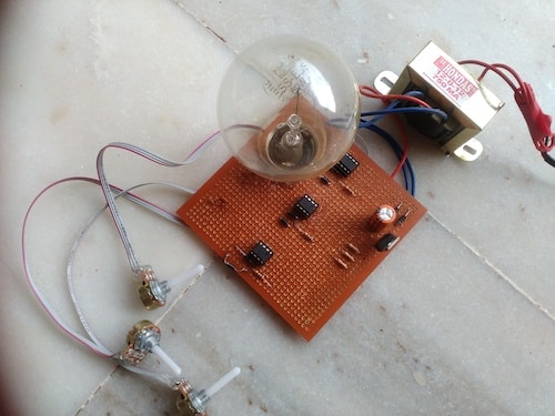
Project prototype is shown below