Introduction
During the experiments with loudspeakers, systems with loudspeakers, transformers, public announcement systems, audio distribution lines and amplifies, etc, we are in need of audio amplifier capable of providing more than 60Vpp at current which can reach and sometimes exceed +-5A.
During the experiments in robotics with DC motors and servo systems we are in need of DC amplifier capable of providing more than 60Vpp at current which can reach and sometimes exceed +-1A.
That short paper is describing a simple and effective solution with many possible configurations which can solve some of the problems stated above.
Description of the circuit
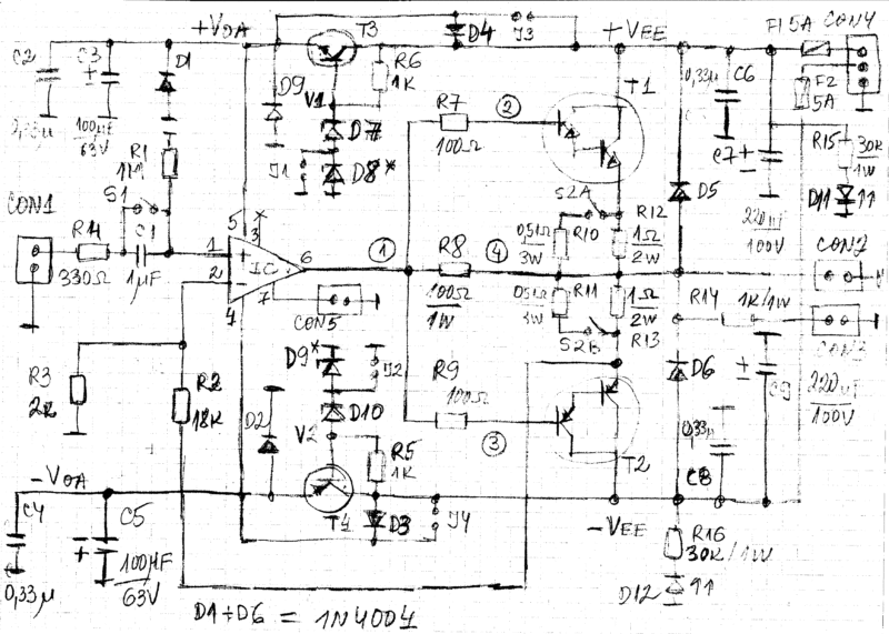
Figure 1 is presenting the circuit of simple and almost universal AC or DC amplifier with OPA452/OPA453 and transistors.
The circuit is built around the powerful operational amplifiers OPA452 (Avmin = 1, SRtyp = +7.2/-10V/us, GBW = 1.8MHz) or OPA453 (Avmin = 5, SRtyp = +23/-38V/us, GBW = 7.5MHz).

Both Amplifies are pin to pin compatible.
The THD of both ICs is typically 0.0008% and that is making them appropriate for a lot of audio applications.
The maximal output current is internally limited to around +-50mA with voltage drop around 5V over the output transistors of the ICs.
The gain of the circuit is fixed to ten and can have any appropriate value.
Av = 1 + R3/R2.
The input resistance is set mainly by R1 to 1 MOhm and that is appropriate for most of the applications.
The amplifier is working in AC mode when the switch S1 is open and in DC mode when the switch S1 is closed.
The output stage of the amplifier consists of transistors T1 and T2.
We can use simple or Darlington transistors as explained below.
The double switch S2A+S2B is giving the possibility to introduce different resistors in the emitters.
That is adding some protection to the output transistors.
These switches are not obligatory but at least one resistor with around 0.22Ohm/3W per output transistors should be present.
Larger resistors are giving better protections.
Resistors in the bases R7 and R9 are around 100Ohm for simple transistors and can be increased to 500-1000Ohm with Darlington transistors.
Resistor R8 should have the minimal applicable value.
It is reducing the THD and the IMD.
DC mode
The only difference between the AC and DC mode of the amplifier is the closing of the switch S1.

That simple difference at the input may lead to significant difference in the power dissipation of the transistors.
It is due to the fact that in DC mode the amplifier can stay indefinitely at any voltage at the output and the dissipation heat can be much higher that the heat in AC mode.
In AC mode we are usually interested in the frequency higher than around 20Hz and consequently, when one of the transistors is dissipating heat, the other transistor is practically OFF.
In order to reduce the dissipation heat, both transistors are working without initial current.
That is increasing a bit the THD and the IMD but the operation of the circuit is safer and thermal protection Is not included.
On-board voltage regulators
The amplifier has two simple on-board voltage regulators built around transistors T3 and T4.
T3 and T4 should be BD139+BD140, preferably TIP41C+TIP42C or better.
Usually there is not need to use heat sinks for them.
If you plan to use the amplifier with input power supplies +-Vee below +-40V these transistorized regulators are not needed.
They can be omitted on the P or you can CBsimple put the jumpers J3 and J4.
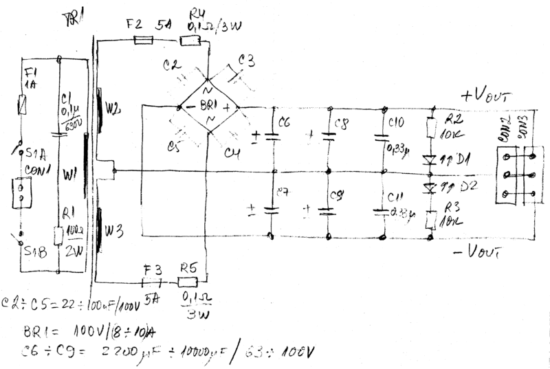
The on-board voltage regulators are needed when the amplifier is used with not regulated power supply as showing on Figure 2 and when we are trying to push the operational amplifier to the maximum.
The voltages V1 and V2 should be between 11V and 40V.
We can use any appropriate Zener diodes to obtain these voltages, e.g. we can use one 18V Zener diode, two 18V Zeners in series, only one 36V Zener diode, one 18V and one 20V Zener diodes in series etc.
The standard Zener diodes from 1.3W series are good enough.
Jumpers J1 and J2 are used for adjustment of the power supplies of the operational amplifier if needed.
Power supply
Special attention should be paid to the power supply of the amplifier.
In the simplest case, we can use the unregulated power supply from Figure 2.
In all cases, the power supplies for the OPA452/453 should be in the range from +-10V up to +-40V.
Consequently, we can use mains transformer TR1 giving from around 2x13V up to 2x45V at the required output current.
In the ideal case, we should use regulated power supply but that is too expensive and rarely required.
The overcurrent protection should be made with fast fuses.
Output transistors
For good performances of the amplifier it is preferable to use transistors with the following parameters:
* maximal continuous collector current above 4A,
* maximal collector-emitter voltage 100V,
* maximal power dissipation at +25C above 65W,
* Darlington transistors with h21e above 1000 at large collector current (e.g. above 3A)
* maximal working temperature more than 150C (preferably 200C).
The industry is offering a large variety of transistors answering to these requirements.
The amplifier is working with large variety of transistors.
A few examples are the couples of ordinary (simple) transistors as TIP41C+TIP42C, TIP3055+TIP2955, TIP-29C+TIP30C, etc.
With these transistors the amplifier can reach easily +-1A of output t current and we should change the fuses F1 and F2 to around 1A.
The amplifier is working also with less powerful transistors as BD139+BD140 but the output current should be limited to around 0.5A and we may have problems with the power dissipation.
The main goal of the amplifier is to work with Darlington transistors, e.g.
2N6287 (PNP, 20А,100V, 160W) + 2N6284 (NPN, 20А,100V, 160W);
TIP102 (NPN, 8А, 100V, 80W) + TIP107 (PNP, 8А, 100V, 80W);
BDX54C (PNP, 8А, 100V, 65W) + BDX53C (NPN, 8А, 100V, 65W);
TIIP127 (PNP, 5А, 100V, 65W) + TIP122 (NPN, 5А, 100V, 65W);
BDW93CFP (NPN, 12А, 100V, 33W) + BDW94CFP (PNP, 12А, 100V, 33W),
and similar or better.
Care should be taken about the following:
1/ The maximal collector-emitter voltage Ucemax of the transistors should be higher than +Vee+abs(-Vee), e.g. if we have +Vee = + 50V and -Vee = -50V we should use transistors with Ucemax >= 100V
2/ The maximal collector current of the transistors should be around two times higher that the maximal working current of the amplifier, e.g. if we wish +-5A from the amplifier we should have transistors for at least 8-10A.
3/ In all cases it is not recommended to push the amplifier with output current above 5A It can produce more than +-10A, depending on the power supply and the transistors!).
4/ The amplifier can work with wide variety of output transistors but the output current and power depends on the selected transistors and the heat sinks.
Conclusions
That short paper is presenting simple universal AC or DC amplifier with OPA452/OPA453 and transistors.
The amplifier has a lot of audio and robotics applications limited only by the parameters of the implementation and the fantasy of the user.
In all cases, care should be taken about the heats sinks and the maximal output currents.
The same PCB can be used with many types of transistors and heat sinks which is making the amplifier almost universal and useful for many applications.
Preferably the power supply and the amplifier should be implemented on two separate PCB – that is the modular approach.
Also, we should have fuses on both PCBs.
We can use that amplifier to built mono and multi-channels (stereo, Quattro, etc) audio systems.


