
This project is based on the AEIOU heuristic framework of Design Engineering Approach.
Design for Performance, Safety and Reliability is ensured in terms of segregation of the low voltage and the high voltage parts of the circuit.
Design for Manufacturability and Assembly is ensured in terms of compact sensors that can be installed within the fields.
Design for Aesthetics and Ergonomics is achieved in terms of remote access by farmers and seasonal and environmental based access to irrigation.
Design for cost and Environment is addressed by correct usage of water, that has now become a prized Natural Resource.
The system can be interfaced via Bluetooth Module using MIT App.
Cost of the Project: ₹1593/-
List of Components Used In Smart Irrigation System
| Component Name | Component Value | Quantity |
| Arduino | UNO | 1 |
| Bluetooth Module | HC-05-09 | 1 |
| Temperature and Humidity Sensor | DHT-11 | 1 |
| Soil moisture sensor | FC-28 | 1 |
| Peristaltic pump | AB11 | 4 |
| LEDs | Red, Green and Yellow | 3 |
| Miscellaneous | ||
| Adaptor | 1 A, 6 V | 1 |
| Connecting Jumpers | ||
| Breadboard | 1 |
1. Sensors
(a) Soil moisture sensor
The soil moisture sensor is used to measure the volumetric water content of soil. It is used to monitor soil moisture content to control irrigation in greenhouses. A moisture sensor is used to sense the level of moisture content present in irrigation field. It has a level detection module in which we can set a reference value.
(b) Temperature and Humidity Sensor
The temperature and humidity sensor is necessary to reduce the watering frequency. That is when the weather gets cooler, less water is needed whereas vice versa in the other case.
2. Relay Module
The relay module is an electrically operated switch that allows you to turn ON or OFF a circuit using voltage and/or current much higher than a Microcontroller could handle. There is no connection between the low voltage circuit operated by the Microcontroller and the high power circuit. The relay protects each circuit from the other. Each channel in the module has three connections named NC, COM, and NO. Depending on the input signal trigger mode, the jumper cap can be placed at high level effective mode which ‘closes’ the normally open (NO) switch at high level input and at low level effective mode which operates the same but at low level input.
3. Peristaltic Pump
A peristaltic pump is a type of positive displacement pump used for pumping a variety of fluids. The fluid is contained within a flexible tube fitted inside a circular pump casing. It is reputed to pump water from a depth of about 31 feet.
Block Diagram
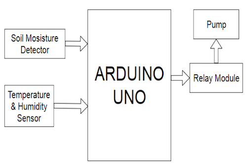
The Model works as follows:
The results of the moisture, temperature and threshold level can be calculated through the sensors used in the project. Analysis of soil parameters can be done and the needed nutrients can be calculated for the soil. The need of water supply of the soil can be calculated and hence appropriate irrigation is done through smart techniques.
Featured experimental result and analysis:
System configuration:
This module is used to configure all hardware devices. Soil moisture sensor, Temperature and Humidity sensor, Pump all are connected to major component arduino with Bluetooth connectivity.
Soil moisture and temperature sensing:
In this module we analyze the moisture content in the soil and it’s temperature. According to the sensor values further decision are taken.
Send the results on Arduino serial monitor:
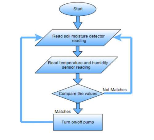
Once the values of temperature and moisture are generated on serial monitor. The threshold can also be notified on serial monitor itself. And if result of Moisture, Temperature and Humidity goes below the threshold value the pump will automatically turn ON and if the level of Moisture, Temperature and Humidity increase upto threshold level of field then pump will automatically turn OFF.
Schematic
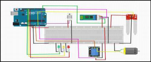
In schematic, Red Wire- Vcc and Black Wire- Ground.
External supply is given to Arduino through 6V-1A Adaptor.
In place of motor, connect 6V peristaltic pump.
Actual Photograph
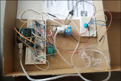
Temperature, Humidity and Moisture Requirements of Major crops are listed:
| Sr. No. | Crop Name | Temperature | Moisture (%) | Humidity(%) |
| 1 | Rice | 21-37 | 20-25 | 60-80 |
| 2 | Wheat | 10-15 | 14-20 | 60-70 |
| 3 | Bajra | 20-38 | 20-25 | 55-70 |
A theoretic study of the parameters considered in our project is summarized by study of different literature materials and papers published.
References for the same is obtained from:
Construction & Testing
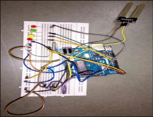
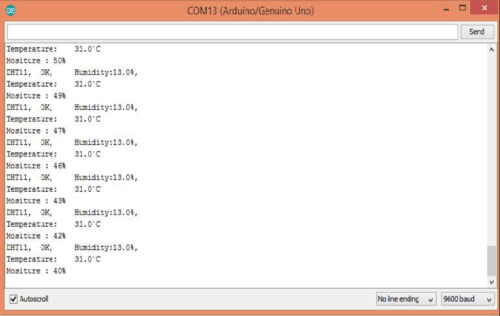
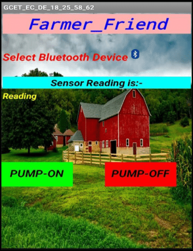

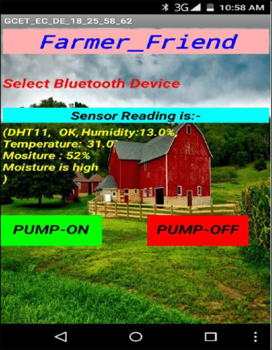
The readings are
DHT11—-OK
HUMIDITY: 13.0%
TEMPERATURE: 31.0%
MOISTURE: 52%
MOISTURE IS HIGH
Flowchart
App Blocks: (MIT App Inventor)


Software Used
Arduino IDE
Code Skeleton
#define Temperature and Humidity sensor A0 // Analog pin A0 of Arduino Uno
int sensor_pin = A0;
int output_value ;
int ledPin1 = 13;
int ledPin2 = 12;
int ledPin3 = 11;
int pos = A1; // Define motor position
——————————————————————————————————————————————
#define Sensor_PIN No.
void setup()
{
(ledPin1, OUTPUT); (ledPin2, OUTPUT); (ledPin3, OUTPUT); // Define the pinModes
pinMode(motorPin, OUTPUT); // set A1 to an output so we can use it to turn on the transistor
Serial.begin(9600); // Baud Rate
Serial.println(“Reading From the Sensor …”);
}
—————————————————————————————————————————————-
void loop()
{
// READ DATA
Serial.print(“Define Sensor, \t”);
int chk = Read the Output of Sensor;
switch (chk)
{
case SensorNameLIB_OK:
Serial.print(“OK,\t”);
break;
case SensorNameLIB_ERROR_CHECKSUM:
Serial.print(“Checksum error,\t”);
break;
case SensorNameLIB_ERROR_TIMEOUT:
Serial.print(“Time out error,\t”);
break;
default:
Serial.print(“Unknown error,\t”);
break;
}
——————————————————————————————————————————————
// DISPLAY DATA
Serial.print(“Humidity:”);
Serial.print(sensorname.humidity, 1);
Serial.print(“%”);
Serial.println(“,\t”);
Serial.print(“Temperature:\t”);
Serial.print(sensorname.temperature, 1);
Serial.println(“`C”);
value= analogRead(sensor_pin);
value = map(value,550,0,0,100);
Serial.print(“Mositure : “);
Serial.print(output_value);
Serial.println(“%”);
if (Humidity value>10)
{
Sensorinput gets HIGH; //green LED ON
}
else {
Sensorinput gets LOW; //Digital Output
}
if (Sensor value>31)
{
Sensorinput gets HIGH; // Digital output
Serial.println(“Tempearture is HIGH”); //yellow LED ON
}
else {
Sensorinput gets Low;
}
if (value>50)
{
Sensorinput gets HIGH;
Serial.println(“Moisture is high”);// RED
}
else {
Sensorinput gets LOW;
}
if (output_value<10) { Serial.println(“output value is low”); Sensorinput gets HIGH; // Digital output delay(x); Sensorinput gets LOW; // Digital output delay(x); } else { Sensorinput gets HIGH; //Digital output } if(Serial.available()>0)
{
char data = Serial.read();
if (data == ‘a’)
{
Motorinp pin gets HIGH; //Digital output
}
else if(data == ‘b’)
{
Motorinp pin gets LOW; //Digital output
}
}
delay(x);
}
//
// END OF FILE
//—————————————————————————————————————————————


We like to learn about smart irrigation system and water leak indication system with gsm sms alerts
Very good project
Thanks for your feedback.
Very Nice Project
Thanks for your feedback.
hey i would like to know how should we connect the peristaltic pumps?
Which connections are used ….male to male……male to female ……..or female to female ?
Bonsoir, mes félicitations à l’équipe EFY
Enfin je voulais réalisé votre modèle là, hélas je rencontre un problème avec votre code pour l’arduino. Pouvez-vous m’aidez s’il vous plait. Merci d’avance.
veuillez élaborer votre requête s’il vous plaît.
I make same project but some error occurs in code while I run it..please sir,/mem help me
This is code skeleton. You have to add library file of sensor which you are using.
If you want code then mail me on [email protected]
I have mailed uh… By name as darshan..
Help me.. .. Little bit
It’s very good project, but but there is a serious problem in the Arduino code. Can not compile it. If you still check the code.
This is code skeleton. You have to add library file of sensor which you are using.
I want the code for the circuit, when the bluetooth is replaced by the wifi module.
can anyone help me…
I want the code for the circuit, when the bluetooth is replaced by the wifi module.
can anyone help me…
My Frend asking me 10k for this project..is that okay? Plz let me know.
I wanted to do same project for my final year..
Is it working properly
Can you please mail the video of the output to me? E-Mail ID is [email protected]
It will be really helpful.
What is the cost of the project?
Amazing one and loved the experience doing it..
Jus a little prob and confusison with the code.Can u help me with that please
Code isn’t compiling. What is the solution?
HI, Ravindra,
Please recheck the code for any error.
can you please email me the code as Arduino file
[email protected]
Hi, the code is already given in the article.
i am beginner in Arduino and the code give a lot of errors even after adding the sensor library.i tried to fix but i cnnot
Can you please provide me the app which you have used…!!!!
sir please mail the code i want to do B.tech project
arduino code is not working ..plss share the code
Hi Aayu, we are rechecking the Source code.
I tried to copy your codes but it is showing this error “ketch_nov08a:15:1: error: stray ‘\342’ in program ”
Please tell me how to fix this error.
What i have to do ?
hello, is there code to run in that mitapp for this project your given code jst show the datra in serial monitor but it is not working in mobile app