


The reference design features a motherboard with RJ-45 connectors, DIMM-format cards, and dual operating modes for efficient Ethernet device powering.
Ethernet is standardized under IEEE 802.3, while Power over Ethernet (PoE/PoE+) follows IEEE 802.3af/at standards. The most common Ethernet network types are 10BASE-T (10MHz), 100BASE-TX (100MHz), and 1000BASE-T (1GHz), all using Category 5 (CAT-5) cables. These cables have four pairs of wires (eight wires total, arranged as pairs 1-2, 3-6, 4-5, and 7-8). In 10/100MHz Ethernet, only two pairs (1-2 and 3-6) are used for data transmission, while 1GHz Ethernet uses all four pairs.
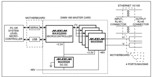
The reference design of PoE by Analog devices comprises a motherboard and up to five DIMM 3.3V-format PC boards. The motherboard is equipped with five 168-pin DIMM-style connectors, RJ-45 connectors/magnetics for 32 Ethernet ports, a ±50V isolated RS-232 transceiver (MAX3250), and a SPI-to-USB controller (MAX3420).

There are three types of DIMM-format cards in this design. The master card features an MAXQ2000 microcontroller, an MAX5020 DC-DC converter to generate +3.3V output from -48V input, and six network power controllers to power 24 channels. The microcontroller communicates with the MAX5945s, which are located either on the master card itself or on additional slave cards, using I²C.
The slave card has six network power controllers to power 24 channels. Additionally, there is a slave B card that holds four network power controllers to power 16 channels. The reference design can operate in stand-alone mode or with a system-level microcontroller.
In the mode with a system-level microcontroller, the user-supplied system processor can either configure settings through I²C or allow the microcontroller to use built-in defaults. The firmware enables the microcontroller to control up to 16 network power controllers on each of the three I²C buses, totalling 48 controllers. The system processor determines which events to report, allowing the designer to have varying levels of control over the system. Settings are retained in nonvolatile memory, and a packet-based error-detecting protocol ensures data integrity through retransmission if necessary.
In stand-alone mode, the MAXQ2000 and its firmware independently manage the operation of the MAX5945s. A PC can set parameters, save them in the microcontroller’s nonvolatile memory, query status, and optionally retrieve stored logs. Communication between the PC and microcontroller occurs via an RS-232 interface or USB.
The design can accommodate 1 to 48 quad controllers, equating to 4 to 192 ports. The firmware automatically detects and configures the number of ports, assuming each MAX5945 has a unique I²C address.
Analog Devices has tested this reference design, which comes with a Bill of Material (BOM), schematics, and other data. The company’s website has additional data about the reference design. To read more about this reference design, click here.
