




A reference design shows how BLDC motor control can combine back-EMF detection, speed control, protection, communication, and debugging functions.
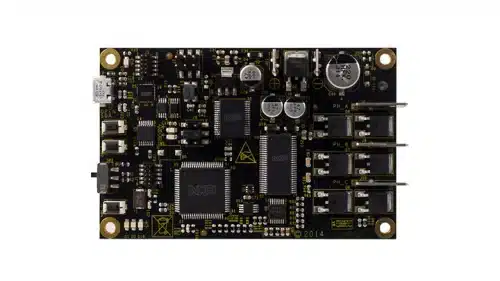
A reference design from NXP Semiconductors shows how a microcontroller can control a three-phase brushless DC (BLDC) motor without position sensors. The design uses back-electromotive force (back-EMF) detection for rotor-position estimation, six-step commutation, closed-loop speed control, current limiting, and motor protection.
For design engineers, the reference design provides an example of combining motor-control algorithms, power-stage control, protection, communication, and debugging functions on one board. It can be used for applications where Hall sensors or other rotor-position sensors may not be required.
The control system detects the zero crossings of the motor’s back-EMF to estimate rotor position. This information is used to determine when the motor phases should be commutated. The design also uses closed-loop speed control to regulate motor speed and dynamic current limitation to control motor current during operation.
The board monitors the DC bus for overvoltage, undervoltage, and overcurrent conditions. This gives engineers an example of adding protection functions alongside the motor-control system.
The design is built around a 32-bit Arm Cortex-M0+ microcontroller. The controller works with a FET pre-driver that provides three high-side and three low-side drive channels for the three motor phases. The pre-driver accepts both 5 V and 3 V logic-level inputs.
A system basis chip provides power-management functions for the microcontroller and supports additional system functions, including sensor interfaces and a CAN transceiver. The board also provides Controller Area Network (CAN) and Local Interconnect Network (LIN) connectivity.
The board was demonstrated with a 24 V, 90 W, 9350 RPM three-phase BLDC motor. The documented board supply range is 8 V to 18 V DC, with the supply voltage affecting the maximum motor speed. These conditions are part of the demonstration setup and should not be treated as general operating limits for BLDC motor applications.
The board provides connections for the motor phases and power supply, along with CAN and LIN, Serial Wire Debug (SWD), and USB connections through OpenSDA. It also includes a connection for a braking resistor, although the documented board does not have the resistor assembled.
The software includes the motor-control algorithm and tools for monitoring and tuning motor operation. It uses functions from an automotive mathematics and motor-control library and integrates FreeMASTER for run-time debugging and visualisation. A motor-control tuning tool is also provided.
Engineers can change the required motor speed through the FreeMASTER interface or switches on the board. The software provides a speed scope for observing motor response, along with other scopes and a back-EMF voltage recorder. These tools can help engineers examine back-EMF waveforms, observe commutation behaviour, and tune the speed-control loop.
NXP has tested this reference design. It comes with a bill of materials (BOM), schematics, assembly drawing, printed circuit board (PCB) layout, and more. The company’s website has additional data about the reference design. To read more about this reference design, click here.