Here is a Simple Audio amplifier using a single IC AN7523. This amplifier gives an output power of 3 watts into an 8-ohm loudspeaker on the power supply of 9Volts.
An IC AN7523 is a 9-pin IC. This IC is very common and available in the market easily and also is not expensive.
| Component | Specification |
|---|---|
| IC | AN 7523 |
| Resistors | R1: 47K |
| R2: 33K | |
| VR1: 10K (preset) | |
| Capacitors | C1: 470µF/25V |
| C2: 1µF/25V | |
| C3: 10µF/25V | |
| C4: 1µF/25V | |
| Miscellaneous | 9V battery |
| 18-pin IC socket | |
| 2-pin socket | |
| 2-pin connector | |
| Wires | |
| 8Ω/3W speaker |
Circuit Description
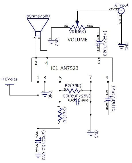
The circuit shown is simple and straight forward. Only one semiconductor IC1 (AN7523) is used in this amplifier and few passive components like C1, C2, C3 and C4 and resistors R1 and R2.

Pin 1 of IC1 (AN7523) is connected to +9Volts power supply. An electrolytic capacitor C1 (470uF/25V) is connected to +9V and ground by facing the positive terminal to +9V and the negative terminal to ground.
Pin2 and 3 of IC1 (AN7523) are connected to an 8 ohms/3W speaker. Pin 3 is connected to the ground.

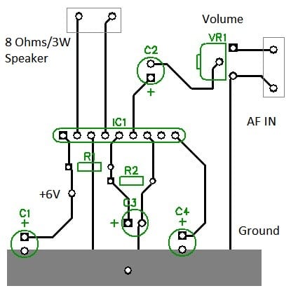
Pin 5 is connected to +9V through a resistor R1 (47K). Resistor R2 ( 33K) and capacitor C3(10uF/25V) are connected between pins 5 and 7. Pin 7 is connected to the ground.
An electrolytic capacitor C4 (1uF/25V) is connected between pin 9 and pin 7 by facing the positive terminal to pin 9 and the negative terminal to the ground.
Pin 6 of IC1 is an AF input terminal. A variable resistor VR1 (10K) is connected to a negative electrolytic capacitor C2 (1uF/25V) and ground. A center pin of VR1 (10K) is connected to the input terminal.
Construction and Adjustment
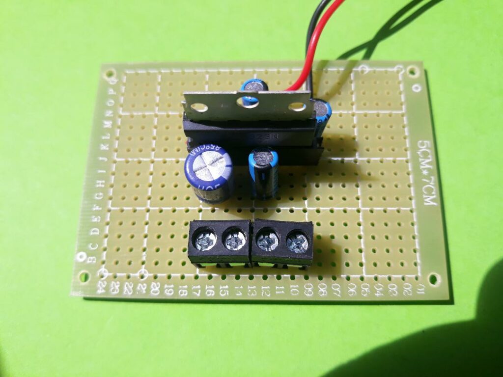
A PCB board given is suitable for building your amplifier. After making a PCB, first take an 18-pin IC and cut it in half. Now put the half of 18-pin IC on a PCB board and solder it.
Do not insert an IC socket during soldering. Take a 2-pin IC socket and connect it to the speaker terminal of the amplifier. Take an AF socket and connect it to an AF input terminal or amplifier. Now take all the remaining components and place them and solder all of them.
Now take a power supply of 9Volts and connect it to the power supply terminal of the amplifier.
Take an 8 ohms/3W speaker and connect it to the speaker terminal of the amplifier. Rotate a VR1 and put it in the middle terminal.
You’ll hear a humming sound coming out from a speaker while touching an input terminal with a small metal screwdriver.
Now your amplifier is working and ready for use.
Also Check Related AF Amplifier Projects