


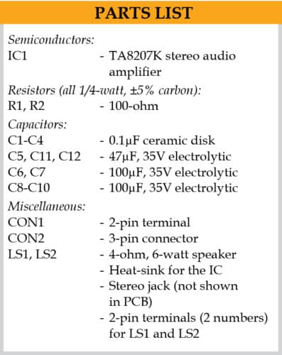
 This simple stereo audio amplifier is based on a 12-pin TA8207K IC, which is inexpensive and easily available. In addition, it requires only a few resistors and electrolytic and ceramic capacitors. You can get output power of about 4.6W for each (left and right) channel using a 12V DC supply.
Circuit and working
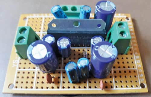
The author’s prototype is shown in Fig. 1 and the circuit diagram is shown in Fig. 2.
As shown in Fig. 2, pins 3 and 12 of IC1 (TA8207K) are connected to +12V terminal of the battery. Pins 6 and 7 of the IC are used for left and right audio inputs, respectively. A 100-kilo-ohm pot can be connected to each input of the amplifier for volume control (not shown in Fig. 2).
Loudspeakers LS1 and LS2 are connected to pins 2 and 10 of IC1 through electrolytic capacitors C8 and C9, respectively. Electrolytic capacitor C10 connected between +12V and ground acts as a noise filter in the supply voltage.


Construction and testing
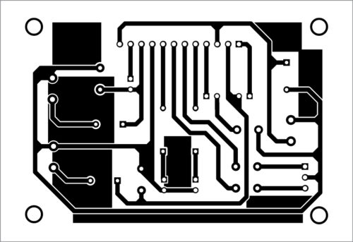
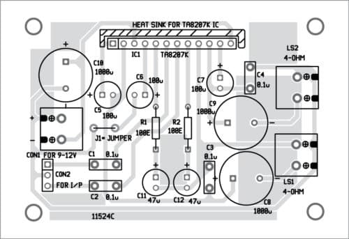
You can assemble this amplifier on a 5cm×6.5cm Veroboard, or on the PCB whose layout is shown in Fig. 3, with its components layout in Fig. 4.
Download PCB and Component Layout PDFs: click here
IC TA8207K, which can be vertically inserted into the Veroboard or PCB, will need a heat-sink to prevent damage to the IC due to overheating that can occur during operation. A small piece of aluminium sheet can be used as the heat-sink.
You may solder two 2-pin terminals (not shown in Fig. 2) for the right and left speakers on the PCB or Veroboard. Solder a 3-pin connector on the board for input signals and a small 2-pin terminal connector for the power supply.
After assembling the circuit, connect audio input from your source (MP3 player, computer, mobile phone, etc) across CON2 and two speakers across LS1 and LS2. Connect the 12V battery across CON1.
Calibration and adjustment
You may use a signal generator for calibration and adjustments. If you do not have a signal generator, you may use a small metal screwdriver for testing.
To test, connect the 12V battery and the two speakers to the amplifier. Pick up the screwdriver and touch it gently on any of the inputs at 3-pin connector (CON2); you should hear a humming sound coming from the speakers.
If you have a signal generator, you can switch it to 1kHz frequency and touch its probe to left and right input points of the amplifier one by one. You should hear an amplified audio tone from the speakers.
Now you may connect audio output of your source of signal to CON2 and enjoy noise-free amplified music.
Raj K. Gorkhali is an electronics hobbyist and a regular contributor to EFY
This article was published in March 2021 EFY Express Issue.

Which solder flux and solder wire is best for the Pcb boards?
Solder flux from Noel and Glare India are found good enough for hobbyist.
Bharti, Amico, TINNZTES, Globomotive and Kester solder wires are some popular ones.
These brands are based on personal experiences and reviews online and not necessarily the best ones.
Pcb layout file can’t be downloaded for this project and Tda1517 amplifier project, tda2616 amplifier project and La4425 amplifier project. Please see
If you are unable to download the source code, please try to open the page in incognito mode and retry or temporarily turn off the antivirus before downloading.