This FM transmitter design is one of the simplest you can build. No tuning is required, as the transmit frequency is crystal-locked at 90MHz. This eliminates the common frequency drift seen in LC-based FM transmitters. Whether you’re streaming tunes or just testing radio waves, this transmitter design is reliable and efficient, without the hassle of manual frequency adjustments.
Circuit and Working
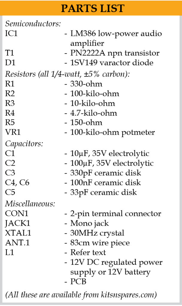
The simple FM transmitter is built around low-power audio amplifier using LM386 (IC1), transistor PN2222A (T1), 30MHz crystal (XTAL1), varactor diode 1SV149 (D1) and a few other components. Inductor L1 is a three-turn coil made with 20SWG wire that has 8mm diameter with half-turn taping.

Tank circuit at the collector of T1 comprising inductor L1 and capacitor C5 is tuned to three times the crystal frequency, or 90MHz. Third harmonic of 90MHz is boosted and coupled to a wire antenna via capacitor C4 for transmission that can be picked up by an FM receiver thirty to fifty meters away.
The audio amplifier formed around IC1 has a gain of twenty. Its frequency modulates the oscillator by varying the capacitance of varactor diode D1, which is connected in series with XTAL1 via resistor R2. Potentiometer VR1 sets frequency deviation and should be adjusted for best sounding audio and low distortion. The transmitter accepts audio input from such external devices as a computer, music player or cellphone. Use an 83cm-long piece of wire for the antenna.
Construction and Testing
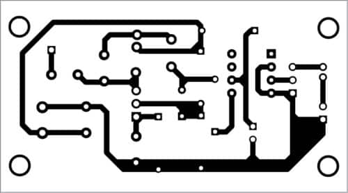
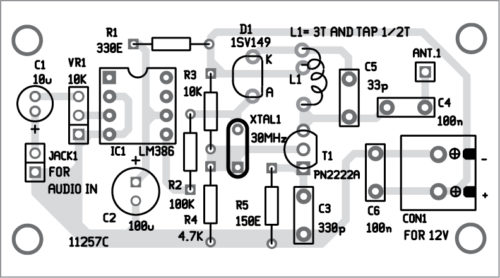
A PCB layout for the simple FM transmitter is shown in Fig. 2 and its components layout in Fig. 3. After assembling the circuit on the PCB or Veroboard, enclose it in a suitable plastic box. Use a shielded cable for input audio connection for hum-free signals.


For downloading PCB and component layout PDFs: Click here
Audio quality of the transmitter is decent, and fidelity is good enough for music. Connect 12V DC regulated power supply across connector CON1.

Connect the audio input at JACK1 from a computer, music player or cellphone. You can listen to the audio on an FM radio by tuning to 90MHz frequency band.
Related FM Transmitter Projects:
Joy Mukherji is an electronics hobbyist who likes designing radio frequency circuits
This article was first published on 3 March 2020, and updated on 22 October 2024


Is it okay to use 27MHz Crystal Oscillator?
Yes. Replace C5 accordingly for resonance at 3rd or 4th harmonic of 27MHz (81 and 108MHz). Replace C5 with a trimmer cap and tune for maximum range and best sound.
If ISV149 is hard to get then try using an IN4007 or several of them in parallel.
Very wrong circuit fm transmitter vertical 1sv149 vse
Buy it works fine with great audio fidelity.
Iam looking for one which can broadcast at a range of 30km
88.8mhz
Please don’t make ignorant comments. The varactor diode is properly reversed biased by the LM386. It’s not a wrong circuit but good design since the audio fidelity is excellent and even music sounds good. ISV149 is able to pull the XTAL frequency a lot but if it’s not available then try other Varicap diode in its place or an IN4007. These rectifier diode make good varicaps.
Nice simple circuit. Going to build this myself.
can i replace 30mhz with 32 mhz and L1 with fixed 1uh inductor and c5 2.7pf to receive at 96mhz. Also tell me more about 1sv149 alternative.
Yes you can do that. ISV149 have high fidelity sound and music sounded awesome too. You can just use an IN4007 diode in place of varactor. I’ve one more circuit of crystal tx. Email me [email protected]
Excellent idea. Using a large value coil and low value capacitor will raise the Q of tuned circuit. I used a 2n3904 and its collector to emitter capacitance is 4.5p so your 2.7p would be added to it giving you a total value of 7.2pf. To resonate that on 96MHz you would need a coil of 0.381uH. Hope this helps.
Can we use 2N3866 or 2SC1971 instead of PN2222A in order to increase the range?
No you cannot. The circuit is not suitable for driving an external VHF amplifier either as its output contains a lot of harmonic energy. But my other project crystal locked fm transmitter has a pure signal so you can connect it to a 2n3866 amplifier for more power. I’ve developed a circuit where 2 parallel PN2222As are delivering half a watt of power on the FM band. Will publish it soon.
hi , nice circuit !!!, one question, it can be use to Radio control devices via different tones ?
Yes why not. Make a receiver with TEA5767 and Arduino. Dtmf tones can be used.
Hi, do you think this circuit can work with a 10 or 20 Mhz crystal? Thx
Try 20mhz crystal and in4007 diode as varactor diode.
thank you
Did it work?
what are the regulation and guidelines regarding use of mini fm transmitter in India. In other countries these are allowed by law upto certain field strength.
No transmissions are allowed without valid license. But there is no enforcement of the law. One is free to run 1KW of RF power at 100MHz and unless you’re interfering with local FM channels there should be no problem at all. Spain is also full of FM pirate radio stations but authorities don’t care. In USA it’s a different story thou
since the fines can be hefty ($50,000).
Sir good cercuit design. Whats the range of this transmitter. Sir from wher e i can get complete pcb with component. Thanks
Hi nice circuit I have a couple of questions, in the circuit diagram VR1 is 10K in parts list VR1 is 100K, which is correct? also in the circuit diagram R1 And R5 have the letter E after the value what is this?
You can use VR1 with 10K or 100K but during testing we have used 100K. The letter E for R1 and R5 simply means ohm. That is, R1=330E=330-Ohm and R5-150E=150-ohm.
what do i require for me to create an fm studio transmitter with range of 20kilometres.a simple one
High antenna. 150 feet. And 10W of power at least to cover 20km. Circuit will he complex
What type of FM generation is this. Direct or indirect type. Is it NBFM or WBFM. What is the frequency deviation ? please put all the details. I was searching for such RF projects for my final year project. can you please help me.
please provide your contact mail, fb, insta or linkedin. or contact me at [email protected]
can I use bc 547 or 2N2222 instead of the above transtor I can’t manage to get it
Yes, you can use 2N2222 or BC 547. You can also use 1N4007 diode in place of 1sv149 diode.
can i get some more detailed information about this project, it will help me for project report.
Kindly share an email to onedit@efy
I made this using 27mhz crystall but I can’t get the signal on my FM reciever any help would be appreciated 🙏🙏 I have done everything as per the circuit
Email me at [email protected] I’ll help you out.
Author here. An alternate circuit using 1N4007 as varactor https://ibb.co/W3stbpb