


Often, we forget to switch off some of the electrical devices in our houses and offices after their usage, especially those with short-duration requirements such as bathroom exhaust fans and lights. This leads to a waste of electricity and increased bills.
To overcome this problem, we present a simple interval timer circuit. When this circuit is connected between the power supply and the load, it automatically switches off the power supply to the load after a preset time (in this case 15 minutes). This ensures that the devices are used only for the necessary amount of time, resulting in energy savings.
POC Video In English:
POC Video In Hindi:
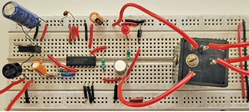
To switch on the device again, one must switch off the circuit and then switch it on to get another preset time usage. Fig. 1 shows the prototype tested in the EFY lab.

Interval Timer Circuit and Working
Fig. 2 shows the circuit diagram of the interval timer. It is built around a 230V AC primary to 12V, 1A secondary transformer (X1), five 1N4007 rectifier diodes (D1 through D5), CD4541BE (IC1), 12V voltage regulator LM7812 (IC2), npn relay driver transistor 2N2219 (T1), a 12V one changeover relay (RL1), and a few other components.

I will be facing so many problem to making simple interval timer circuit
in your circuit diagram you are taking two 10k resistance and in your breadboard you connect 5.6 k resistance . I am not understand about CON2 AND CON3 where they are connected .
Refer the circuit diagram both 5.6(R3) and 10K(R5) resitors are used in the project.
Connector CON2 is used to conncet the load such fan, motor etc. While the Connector CON3
is used to connect 230V AC to operate the applinace.
After all connection I did not get the output what should I do .
LED will not blow . Can I connect the light , other load in the circuit to check the timer circuit .
Sorry to hear that you’re facing issues with your circuit.
Here are a few steps you could take:
1.Ensure that all connections are correctly made according to the circuit diagram.
2. Check the CD4541BE timer is not faulty
3.Verify each component in your circuit is functioning as expected.
4.Confirm that your power supply is providing the required voltage.
5.As circuit involves a timer, review the timer settings and wait upto that time to glow the LED/energised relay.
6.Use a multimeter to measure voltages at various points in the circuit.
Best of luck, and I’m here to help if you need further assistance!
Thank you sir for your reply I will check all the point
You are most welcome.