


 Real-time clock (RTC) integrated circuits (ICs) are used for reasonably accurate time displays. The accuracy of RTCs mostly depends on the crystal. In a long run, a small-time deviation will be observed in the RTC circuit due to seasonal and atmospheric temperature changes. In case of a Global Positioning System (GPS) clock, the time/time stamp is received from the satellite(s) and is highly accurate. This project is based on a low-cost GPS clock using AVR ATmega8A microcontroller (MCU).
Circuit and working of Low-Cost GPS Clock
Circuit diagram of the simple and low-cost GPS clock is shown in Fig. 1. It is built around ATmega8A (IC1), NEO 6M GPS receiver module (GPS1) along with an antenna, 16×1 LCD (LCD1) and a few other components.
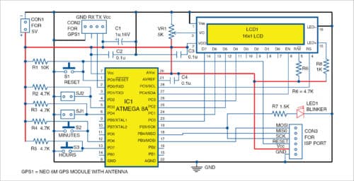
NEO 6M GPS receiver module receives National Marine Electronics Association (NMEA) data continuously and transfers the same to ATmega8A MCU. The MCU processes the data and picks the date stamp from the received data string. The following data format is searched in the received data, which is used to pick the time stamp:

$GPGGA, 143621, . . . . .
The MCU checks for the keyword $GPGGA and reads the next six characters of the received string and displays it on LCD1. This process repeats in a cyclic process, and the latest time is displayed.

The time stamp received is always in Universal Time Coordinated (UTC) format, which matches with Greenwich Mean Time (GMT). To convert it to local time, add proper time constant to UTC time, which will depend on the country and city. In the program, the local time constant for Indian time is set to +5:30, but you can modify it to set a different value.
The local time constant is declared in C program as:
int ADJ[2] = {5,30};
Initial setup
After connecting the circuit, upload GPSclock.hex file to ATmega8A MCU using any AVR programmer through ISP port. Once the program is loaded, blinker LED1 will glow for one second followed by ‘NEO 6M GPS Clock’ message on LCD1. By default, it will display in UTC format.
To change to local time constant, press any switch (S2 or S3) to display the existing value. By pressing hours and minutes switch, the local time constant changes. If no switch is pressed for more than four seconds, the value is saved in EEPROM of the MCU.
The GPS module will initialise and try to connect to the satellite for data reception. This may take some time, say, three to five minutes. LCD1 will display “Connecting..” till the data is received from the satellite. Once the data is received, the time will be displayed on LCD1 in HH:MM:SS format continuously. In case GPS module is not connected, or is giving a connection error, ‘NO GPS MODULE’ message will be displayed on LCD1.
Use shorting jumpers SJ1 for 12/24-hour format and SJ2 for local/UTC time to be displayed. LED1 will indicate that the MCU is processing the received data. Potmeter VR1 is used for adjusting the contrast for LCD1.
Construction and testing
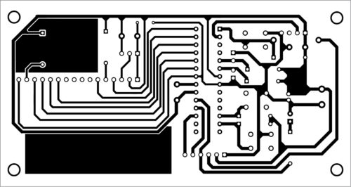
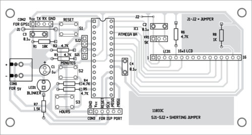
An actual-size PCB layout of low-cost GPS clock circuit is shown in Fig. 2 and its components layout is shown in Fig. 3.
Download PCB and Component layout PDFs: click here
Download source folder
Assemble the circuit on the PCB and connect 5V across CON1 to operate the circuit. Enclose the circuit in a suitable box and connect GPS1 across CON2. Connect the antenna to GPS1. Place the unit at a suitable location along with LCD1. Jumpers J1 and J2 shown in the PCB can be any conductor wires. Connect these before switching on the circuit.
Jumper setting
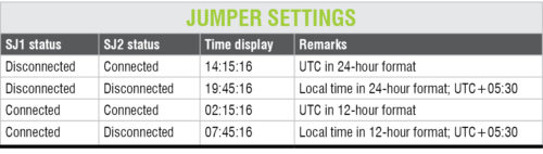
Connect SJ1 in 12-hour format, otherwise it will be set in 24-hour format by default. Connect SJ2 for UTC time, otherwise it will be set in local time (UTC+5.30).
For example, the time stamp received by the GPS module is 14:15:16, which is in UTC time in 24-hour format by default. Now, LCD1 will display the time as per the settings for SJ1 and SJ2, as shown in the table, assuming the local time constant as +05:30:00.
To change the local time, press minutes and hours switches (S2 and S3, respectively) during initialisation of the system when NEO 6M GPS message appears on LCD1. Change local time constant only once.
Fayaz Hassan is manager at Visakhapatnam Steel Plant, Visakhapatnam, Andhra Pradesh. His interest includes MCU projects, mechatronics and robotics.

where the code please
Hi Ibrhimattaka, the source folder is updated on the website.
Hi Mr. Fayaz Hassan!
I Am György Krasznai from Hungary. It is a very nice project!
Fuse bit settings would be required to program the processor. Can you give these?
Thank you.
György
hello mehdi from iran i could not find sourcemeh folder in your site ? tanks for your concern .
Hi Mehdi, you can download the Source Code here.
Dear Sirs,
the parts list is incorrect.
Please can you fix this?
Regards
Mitsos
Thank you for your comment, we have checked and corrected the parts list.