


 White noise is widely used during the testing of preamplifiers, filters, power amplifiers, etc. So white noise generators are required at least for the audio signal range. These generators exist in the market but usually are quite expensive. Here is a simple and low-cost white noise generator made with a Zener diode and three popular high-gain transistors that can be made easily.
This noise generator can be used individually for a wide variety of testing purposes. Also, it can be used with additional filters to produce such ‘coloured’ noises as pink noise, grey noise, blue noise, etc. The targeted applications for this noise generator are up to around 100kHz.
Circuit and working
Circuit diagram of the white noise generator is shown in Fig. 1. It is built around three BC547 transistors (T1 through T3) and a 6.8V Zener diode (ZD1). It requires a 15V DC power supply.

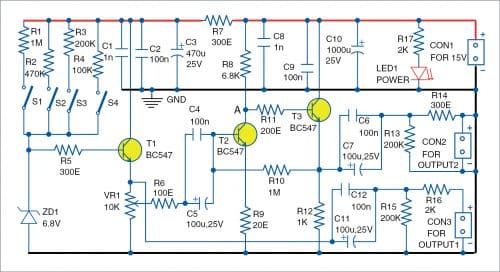
Breakdown voltage of Zener diode ZD1 should be lower than the power supply voltage Vcc, which is 15V in this case. Usually, there is no need to select the Zener diode according to the noise to be produced. But, if required, you can change the Zener diode, transistors, and the LED to suit the kind of noise to be produced.
The noise produced by the Zener diode depends on the current through the diode. Here we have four options for that current, which can be selected through switches S1, S2, S3, and S4, or jumpers in their place to save cost. Transistor T1 works as emitter-follower because at low currents, the Zener diode has high internal resistance.
The circuit produces two outputs—Output 1 for the white noise buffered from T1, and Output 2 for the amplified white noise from transistors T2 and T3. Pot VR1 is used to adjust amplitude of the noise that is amplified by T2 and T3.
Transistor T2 works as voltage amplifier, increasing the amplitude of the noise. The voltage gain depends mainly on the resistors connected to the emitter and collector of T2. The voltage at collector of T2 (point A) should be around half of the power supply voltage. To obtain that you may need to change the value of feedback resistor R10. Transistor T3 works as emitter-follower, providing low output resistance at Output 2.
The maximal amplitude depends on the Zener diode and the power supply. The power supply (Vcc) should be within the range of 12V to 25V. Higher Vcc is better as it can produce higher output signal in case of need. The circuit will work well even with 9V power supply but the Zener diode breakdown voltage rating in that case should be below 6V (During testing at EFY Lab, a 15V power supply and a 6.8V Zener diode were used.)
Construction and testing
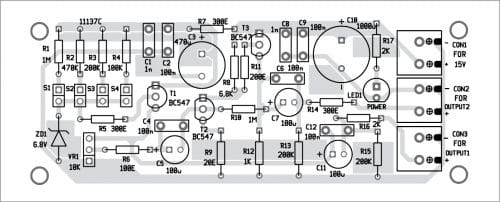
A PCB layout for this simple white noise generator is shown in Fig. 2 and its components layout in Fig. 3. Assemble the circuit on PCB. Connect 15V DC supply to the PCB at connector CON1. Connect switches S1 through S4 to the PCB using suitable wires. The two outputs are available at CON2 and CON3 connector points.
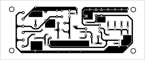
Download PCB and Component Layout PDFs: click here
Petre Tzv Petrov was a researcher and assistant professor in technical University of Sofia, Bulgaria and expert lecturer in OFPPT (Casablanca), Kingdom of Morocco. Now he works as an electronics engineer in the private sector in Bulgaria