Sunday, October 1, 2023

Simple Security Code Lock Circuit

By Suresh Dwivedi

- Advertisement -
efy tested

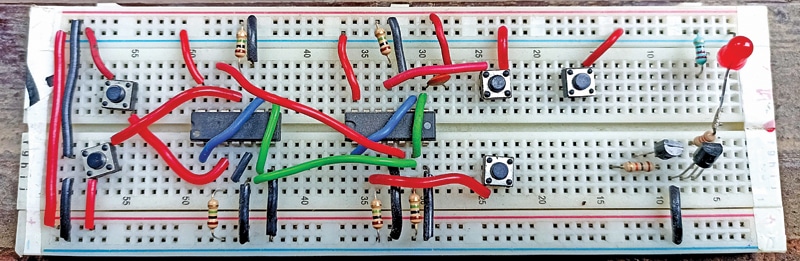
The circuit described here is an electronic combination Security Code Lock. It opens only when you press four keys in the correct sequence (referred to as a code) out of a total of eight keys installed at your entrance door. If you press the wrong key sequence, the circuit resets, and the lock will not open. The author’s prototype is shown in Fig. 1.

Security Code Lock Circuit on breadboard
Fig. 1: Prototype of the lock tested on a breadboard

POC Video In English:

POC Video In Tamil:

Security Code Lock – Circuit and Working

The circuit diagram of the security code lock is shown in Fig. 2. The circuit consists of step-down transformer X1, bridge rectifier BR1, 12V voltage regulator LM7812 (IC1), dual-D flip-flop ICs 4013 (IC2 and IC3), rectifier diode 1N4007 (D1), PNP transistor BC557 (T1), npn transistor 2N2219 (T2), 12V single changeover relay RL1, and a few other components.

Security Code Lock Circuit diagram
Fig. 2: Circuit diagram

This project operates with 12V DC which is derived from the 230V AC primary to 15V, 500mA secondary step-down transformer X1. The 230V AC mains is connected to the primary of X1 via CON1 in the circuit. The secondary of X1 is 15V AC, which is connected to bridge rectifier BR1 for rectification and filtered by capacitor C1.

- Advertisement -

The rectified and filtered voltage is then supplied to regulator IC LM7812 (IC1) to regulate it to 12V for enabling the circuit. The glowing LED1 indicates that 12V is available to enable the circuit.


WHERE IS THE REST OF THIS ARTICLE'S CONTENT?

This is PREMIUM content, which means that only
REGISTERED users of our website can read it, by logging in.

If you ARE a registered user, CLICK HERE to login.
Else, CLICK HERE to register for FREE!

SHARE YOUR THOUGHTS & COMMENTS

Electronics News

Truly Innovative Tech

MOst Popular Videos

Electronics Components

Calculators