


 This simple shortwave transmitter is easy to construct and can be used to transmit speech on the lower shortwave (SW) band of 5MHz to 12MHz with appropriate choice of crystals. It is a good project for a beginner.
Circuit and working
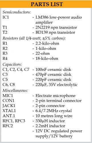
The circuit diagram of simple shortwave voice transmitter is shown in Fig. 1. It is built around power transistors 2N2219 (T1), BD139 (T2), and low-power audio amplifier LM386 (IC1).
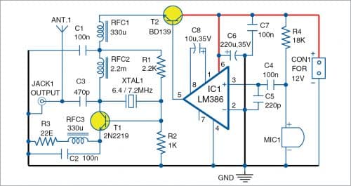
Transistor T1 is configured as a pierce oscillator whose frequency is determined by XTAL1. Resistors R1, R2, and R3 provide biasing and feedback is provided by the crystal. A carrier wave of 6.4 or 7.2MHz is generated at collector of T1, which is coupled to antenna via capacitor C3. RF choke RFC2 lets DC voltage pass through while presenting a high impedance to RF. Additional filtering is provided by RF choke RFC1 and capacitor C1. The modulator is built around low-power audio amplifier chip LM386 (IC1). It offers high audio gain of 200, which is set by capacitor C8.

Audio signal from microphone MIC1 is amplified and fed to an emitter follower current booster transistor T2. Transistor T2 ensures that very little power is drawn from IC1, thereby keeping audio distortion to the minimum. Transistor T2 also series modulates the oscillator by varying its supply voltage in accordance with the audio signal. This results in 80 percent modulation of the carrier wave. Output power is only 40mW, but it can rise to 120mW with 80 percent modulation by using a 10-metre long wire antenna for transmission.
Construction and testing
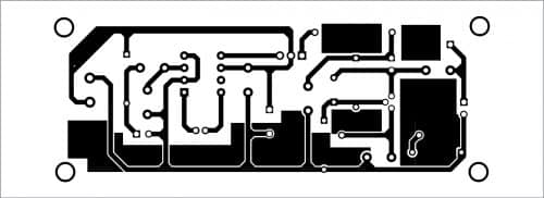
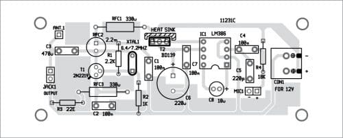
A PCB layout for the voice transmitter is shown in Fig. 2 and its components layout in Fig. 3. After assembling the circuit on PCB, connect a 12V battery across connector CON1 and take audio output from JACK1. The audio can be heard on a shortwave radio receiver after proper tuning.
Download PCB and Component Layout PDFs: click here
Connect MIC1 and speak into it. The same can be listened to on a shortwave radio tuned at 6.4 or 7.2MHz frequency.
You can assemble the simple circuit even on a general-purpose PCB. The RF chokes used are readymade moulded chokes and their values are not critical. RFC1 and RFC3 can be of any value between 100µH and 680µH. RFC2 can be 1mH to 4.7mH. A 7.2MHz crystal was used during testing. Use a 12V hum-free regulated power supply.
After constructing the circuit on PCB, house it in a suitable plastic box.
Joy Mukherji is an electronics hobbyist who likes designing radio frequency circuits

what is the range of this system???