


There are many AM/FM receiver circuits available, but the difficult part is making the coils and tuning the circuits. Without their proper construction and alignment, the circuits do not perform well. This article describes how to build a simple stereo FM Radio Receiver Circuit without tuning components such as inductors, variable capacitors, and ceramic IF filters.
Previously we designed the FM Receiver Circuit with tuning components.
POC Video Tutorial In English:
The FM receiver is capable of receiving 76 to 108MHz FM band with stereo output having good sensitivity and performance. The output is capable of driving a 32Ω speaker directly, which eliminates additional audio headphone amplifiers.
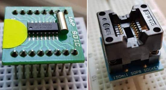
The heart of the circuit is based on IC HEX3653/GS1299/RDA7088. We can use any one of them. All three ICs have the same pinout and function and come in a SOP16 package with a 1.27mm lead pitch. You can check the RDA7088 Datasheet.
We can either use a pitch converter breakout board for ease of using a breadboard, Veroboard, or dot board with a 2.54mm pitch. We can also use a SOIC-16 ZIF socket adaptor with a 2.54mm pitch for easy and quick experimentation.
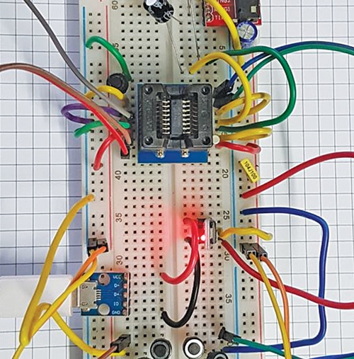
Fig. 1 shows the Stereo FM Radio Receiver Circuit on Breadboard. The components required to build the radio circuit are mentioned in the below table.
| Components Required to Build Stereo FM Radio Receiver Circuit | ||
| Ref. | Descriptions of the components | Qty |
| U1 | RDA7088, HEX3653, or GS1299 in SOP16 package | 1 |
| Y1 | 32.768kHz crystal (2mm x 6mm or 3mm x 8mm) | 1 |
| R1 | Resistor 10kΩ , 250mW (CFR 5%) | 1 |
| C3, C5 | Capacitor 100nF | 2 |
| Antenna | 75cm SWG#22 | 1 |
| C1, C2 | Capacitor electrolytic, 100µF/16V | 2 |
| L1 | Inductor 100nH | 1 |
| C6 | Capacitor 24pF | 1 |
| Breadboard or Veroboard | 1 | |
| SOP16 1.27mm to 2.54mm adaptor, or ZIF socket | 1 | |
| Jumper wires | ||
| 3V DC or AMS1117-3.3 | ||
As can be seen, the radio receiver requires very few external components, yet supports the worldwide frequency band of 76 to 108MHz.
FM Radio Receiver Circuit – Features
- Less than 5-second full band seek time
- Low-cost 32.768kHz crystal for RCLK
- Digital automatic gain control (AGC)
- Direct 32Ω speaker driving
- Simple SOP16 package
- 1.8V to 3.6V DC voltage operation
- Low current consumption of 17mA at 3V
Stereo FM Radio Receiver Circuit Diagram
