


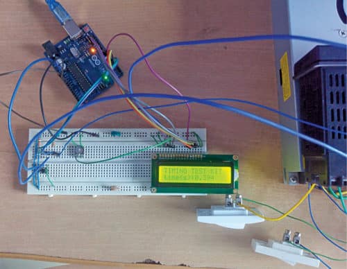
 Presented here is a simple timer kit built around an Arduino Uno board. It can be used to measure the time delay duration of devices like timer relays, circuit breakers, and other sequential logic circuits. This timer will be a low-cost solution for laboratory/industrial requirements. The author’s prototype is shown in Fig. 1.
Circuit and working
The schematic diagram of the kit, shown in Fig. 2, has few components besides the Arduino Uno board (Board1). It has external input contacts to start and stop the timing measurement. Both the contacts can be either normally open (N/O) or normally closed (N/C). The change-over operation of start contacts initiates timing measurement, and of the stop contacts stops the measurement.
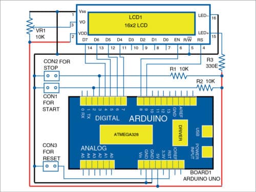
The measured time is displayed in seconds on LCD1. Measurement in the range of milliseconds to several minutes is possible. It is tested with known values set in a mini programmable logic controller (PLC.) A reset button (connected across CON3) is provided to reset the display to zero and start a fresh timing measurement.

The software (timing_kit.ino) is written in Arduino programming language using Arduino IDE version 1.8.5. The sketch/program uses the interrupt and millis ( ) functions of the Arduino. Ensure that you select the correct board from the Tools menu in Arduino IDE before uploading the timing_kit.ino sketch file to the board.
Construction and testing
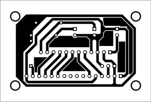
Assemble the circuit on a breadboard or PCB. An actual-size PCB layout for the timer kit is shown in Fig. 3 and its components layout in Fig. 4. Connect the Arduino Uno board and LCD1 as shown in the schematic diagram. Make sure that you first upload the source code (timing_kit.ino) to the Arduino Uno board via a USB cable attached to the laptop/desktop.
Connect start contacts to CON1, stop contacts to CON2, and reset push button to CON3. Power on the Arduino Uno board through USB/adaptor power supply. Adjust LCD1 contrast using potmeter VR1 to get a clear display.

Download PCB and Component Layout PDFs: click here
Download Source Code
Press the reset push button before carrying out time measurement. You will get the ‘Timing test kit’ message on the first line and ‘Time(s): 0.000’ on the second line of LCD1. The circuit is basically an up-counter/timer.
Now close the start contacts to start the count. The counted reading will be displayed on LCD1. Depending on your requirement, you can stop the count anytime by closing the stop contacts after a delay. The counting time is displayed in seconds on the left side and in fraction of seconds (in milliseconds) on the right side of LCD1, which is the time duration between the start and stop of the timing test kit.
After assembling the circuit, enclose it in a suitable box with LCD1 display and reset button on the front panel. Start and stop connectors can be provided on the rear side of the panel for manual control or PLC connections. Now the kit is ready to use for measuring the timings of timer relays, circuit breakers, and similar devices.
Note. Only potential-free external N/O or N/C contacts shall be used as the start and stop contacts with a common ground.
P. Balasubramanian is a retired scientific officer from Nuclear Power Corporation of India Ltd (NPCIL). He has 32 years of experience in the field of electrical maintenance at Madras Atomic Power Station, Kalpakkam and Koodankulam Nuclear Power Project, Koodankulam. His area of interest includes microcontrollers and power electronics.

Got mini project topic of this sem. Thanks
You are most welcome.
Dear Sirs,
the download link for the PCB and Component Layout seems to be broken.
Please can you fix this?
Kind Regards
Mitsos
Please refresh and retry.
Dear Sirs,
the download link for the PCB and Component Layout is not correct.
The downloaded file is: Simple-Timer-Based-On-Arduino.zip (587 bytes)
Please can you fix it?
Kind Regards
Mitsos
The file is correct, please recheck.