


 This generator produces audible signals to test microphones and codecs used in audio amplifier equipment. This simple triple sine wave generator can also be used for testing other audio systems, including VoIP (Voice over Internet Protocol) equipment.
The equipment for transmitting speech signals is usually designed to transmit audio signals in the range of around 300Hz to 3400Hz. Testing of such equipment is usually carried out using three frequencies—300Hz, 1000Hz, and 3400Hz. During the tests, we normally use separate and mixed frequencies.
Circuit and working
The circuit diagram of the simple triple sine wave generator is shown in Fig. 1. It is built around three dual audio operational amplifiers NE5532 (IC1 through IC3), a dual power supply, and a few other components.

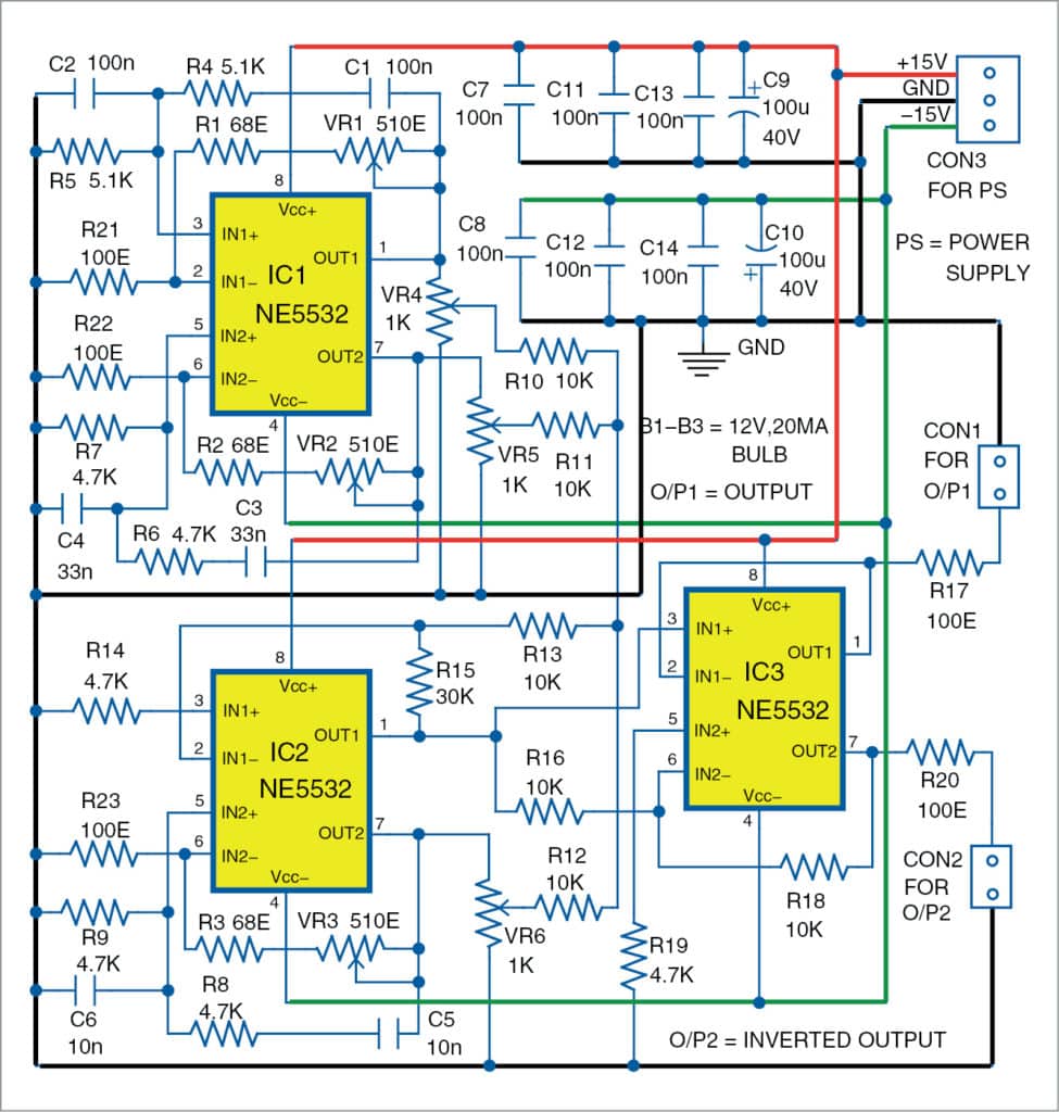
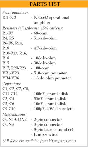
You can use an operational amplifier like NE5532A, RC4560, or any similar or better one capable of driving loads of up to 600-ohm.
The circuit has three sine wave generators with Wien bridges and three operational amplifiers (IC1 through IC3). The frequencies of the oscillators are shown in the table above.
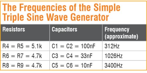
It is better to use resistors R4 through R9 and capacitors C1 through C6 with tolerance of ±2 per cent or better. We can calculate the frequency of oscillations by using the formula for the standard Wien bridge oscillator.
Pins 1 and 7 of IC1 are outputs of the first and second oscillators, respectively, while the output of the third oscillator is obtained from pin 7 of IC2.
All the three signals produced by these three oscillators are mixed at IC2. Pin 1 through pin 3 of IC2 and associated components operate as a signal mixer.
The amplitudes of input signals at pin 2 of IC2 are adjusted with potentiometers VR4, VR5, and VR6.
The triple sine wave generator has two outputs. The forward output is buffered by first op-amp formed by pin 1 through pin 3 of IC3, and the inverted output is buffered with second op-amp formed by pin 5 through pin 7 of IC3. Sine wave output (O/P1) is available across CON1, and its inverted output (O/P2) is available across CON2.
The triple sine wave generator is operational in ±5V to ±15V range, but it is better to use it with power supply in the range of ±7V to ±15V only.
Construction and testing
An actual-size PCB layout for the triple sine wave generator is shown in Fig. 2 and its components layout in Fig. 3. Assemble the circuit on the PCB. Connect ±15V dual power supply across CON3, and your circuit is ready to use.
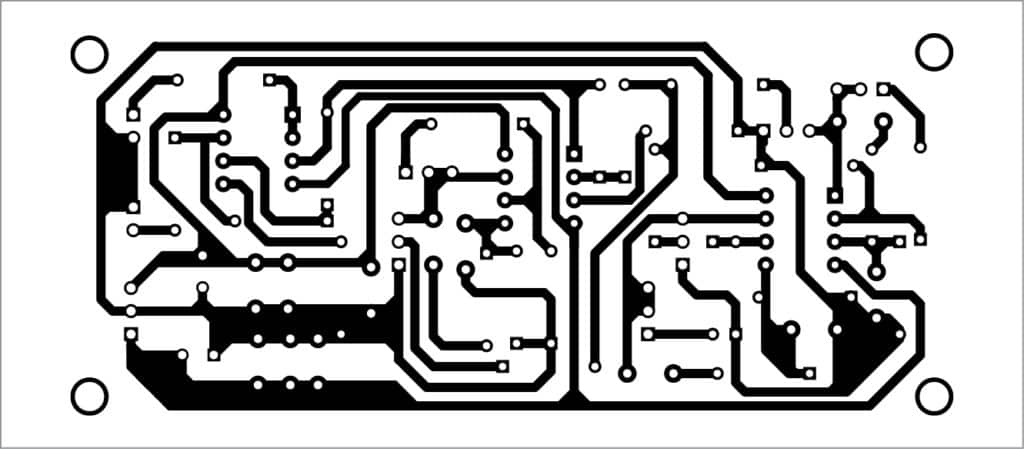
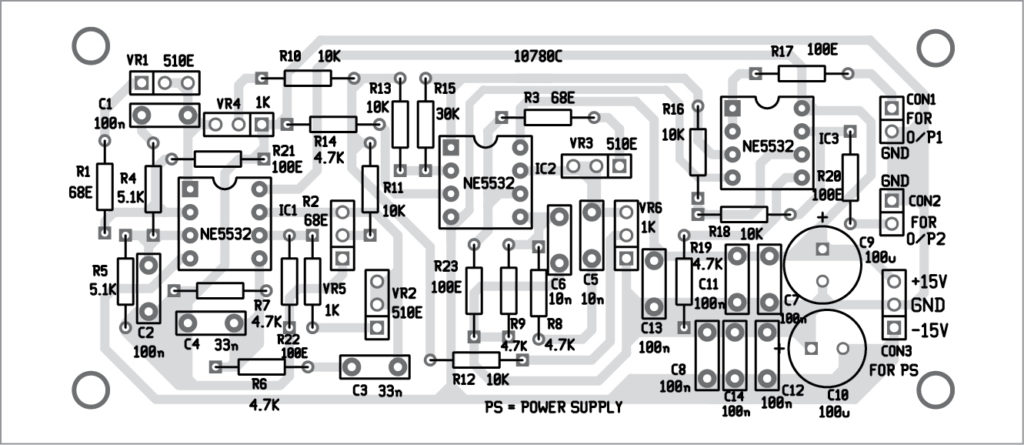
Download PCB and component layout PDFs: click here
The given circuit can produce three sine-wave signals (312Hz, 1026Hz, and 3400Hz) simultaneously, as listed in the table. These outputs are available at CON1 and the inverted outputs at CON2 connector.
The circuit needs a simple adjustment of the amplitude for each oscillator. The potentiometers VR1, VR2, and VR3 are used to adjust the output amplitude of the oscillators around IC1 and IC2. We can replace these potentiometers with appropriate fixed resistors.
Petre Tzv Petrov was a researcher and assistant professor at the technical University of Sofia, Bulgaria, and expert lecturer in OFPPT (Casablanca), Kingdom of Morocco. Now, he is working as an electronics engineer in the private sector in Bulgaria.

Please I need the full material or this project titled design and construction of simple triple sine wave generator . It my project topic which has been approved.
Please mention your exact requirement and send it to our support team at : [email protected]
I need the soft copy of the project for my final year project defence. Thanks
Hi Emmanuel, you can just print or save the article on your computer.