 In this project, temperature data is logged in real time in MATLAB workspace by building a model using Arduino IO Library in Simulink. Process parameter measurement carried out for experimental research and analytical testing generally needs to be saved in real time in order to conduct further analysis.
This is particularly relevant in the domain of instrumentation engineering where parameters such as temperature, pressure, flow rate, pH, viscosity, etc, are measured and then saved on the computer in order to analyse the dynamics of the process, or for fault diagnosis.
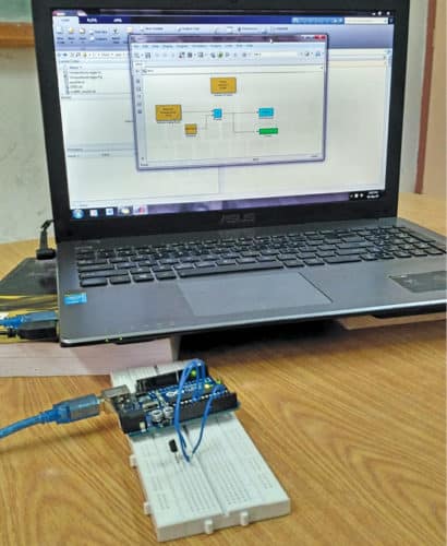
This project is based on Arduino Uno and temperature sensor LM35 IC. The authors’ prototype is shown in Fig. 1.

Hardware and construction
The components used in this project are:
Arduino Uno
Arduino Uno is an AVR ATmega328P microcontroller (MCU) based development board with six analogue input pins and 14 digital I/O pins. The MCU features 32kB ISP flash memory, 2kB RAM, and 1kB EEPROM. The board provides the capability of serial communication via UART, SPI, and I2C. It can operate at a clock frequency of 16MHz. In this project, the analogue pin A0 of Arduino is used to read the output voltage (from pin no. 2) of LM35.
LM35
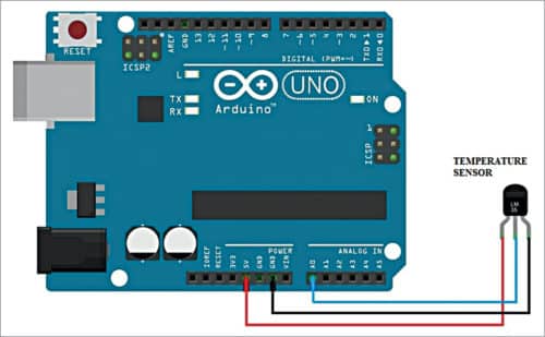
This is a precision IC temperature sensor. Its output voltage is linearly proportional to the temperature (in degree Celsius). LM35 exhibits typical accuracies of ±1⁄4°C at room temperature and ±3⁄4°C over a full temperature range from –55°C to +150°C. This sensor provides a sensitivity of 10mV/°C. In this project, the Vout pin (pin no. 2) of LM35 IC is connected to analogue input pin A0 of Arduino. Pin numbers 1 and 3 of LM35 are connected to +5V and GND of the Arduino Uno board, respectively.
The connection diagram of the interfacing temperature sensor with the Arduino board is shown in Fig. 2.
Software
The application program is developed in MATLAB R2014a with the Simulink toolbox. In order to build a Simulink model, ‘Arduino IO Library’ is needed, which can be obtained by installing ‘Legacy MATLAB and Simulink Support for Arduino package’ as explained below:
- Download Legacy MATLAB and Simulink Support for Arduino package from the MathWorks website. Extract ArduinoIO compressed folder
- From this folder, copy the pde folder and paste it in C:\ Program Files (or Program files x86)\Arduino\Examples (path may be different depending on the installation directory of the IDE)
- After pasting the pde folder in the correct location, open Arduino IDE. If you have pasted the folder in the correct location, you would find pde in FileExamplespde
- Open adios code from FileExamplespde
- Connect the Arduino Uno board to your PC. From the device manager, note the COM port at which the Arduino Uno board is installed
- From Tools menu in Arduino IDE, select the board as Arduino Uno and select COM Port number noted earlier
- Upload adios code to the Arduino Uno board by pressing the upload button in IDE
- Copy the entire contents of the extracted ArduinoIO folder to a folder in My Documents (For Windows PC). This step may be different if you are using the latest version of MATLAB
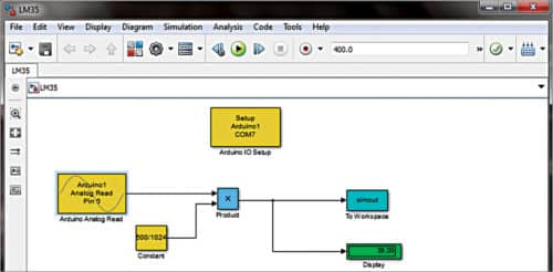
- Open Simulink LM35.slx source code file from MATLAB. The screenshot of the designed Simulink model is shown in Fig. 3
- Double click on the block ‘Arduino IO Setup’ and change the serial (COM) port number (set as ‘COM7’ here) with the corresponding port number in your PC where the Arduino has been installed
- If you want to connect LM35 to some other analogue pin of Arduino, double click on ‘Arduino Analogue Read’ block and set the corresponding pin
- Set ‘Simulation Stop Time’ as per your requirement
- Click on ‘Run’ button in Simulink
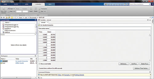
- The corresponding value of temperature can be seen on the ‘Display’ block in the model window. Additionally, the temperature data is also logged in MATLAB workspace variable ‘simout’. When the simulation terminates, the temperature data can be read by double-clicking on ‘simout’ in the workspace window of MATLAB. The screenshot of the temperature (in degC) data saved in MATLAB workspace is shown in Fig. 4.
Download Source Code
Shibendu Mahata is MTech (gold medallist) in instrumentation and electronics engineering from Jadavpur University. He has made several contributions in the domain of signal processing in reputed international journals and conferences.