


 This tutorial demonstrates a different way of interfacing a 4×4 matrix keypad with ATmega32 AVR microcontroller. Keypad is one of the most important input devices used in electronics projects. It is one of the easiest ways to give commands or instructions to an electronic system. But when designing a traditional matrix keypad, you require more number of input/output (I/O) pins. For example, if you are developing a 4×4 keypad of 16 keys, you require eight digital I/O lines of the microcontroller device.
This project uses only a single analogue pin to achieve the same goal, so the remaining pins are available for other purposes.
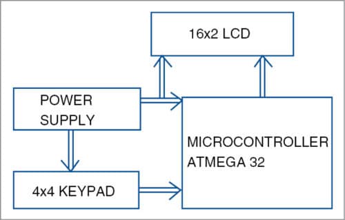
Fig. 1 shows the block diagram of the single-wire keypad with liquid-crystal display (LCD). The system consists of a 4×4 keypad that inputs data to the microcontroller through a single wire, ATmega32 microcontroller for processing the received signal, power supply section and a 16×2 LCD for displaying the keys.

Circuit and working
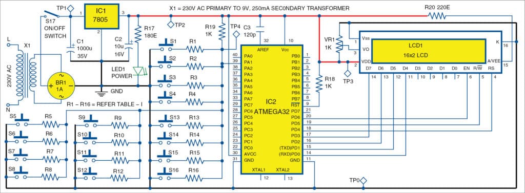
Complete circuit diagram of the single-wire 4×4 matrix keypad using AVR is shown in Fig. 2. It is built around step-down transformer X1, 16 pushbutton switches (S1 through S16), 16 resistors (R1 through R16), a 5V regulator 7805 (IC1), an ATmega32 microcontroller (IC2), an LCD (LCD1) and a few other components. It has three sections: power supply, display and keypad.
Download Original Image
Power supply
The 230V AC mains is stepped down by a 230V AC primary to 9V, 250mA secondary transformer (X1), rectified by a bridge rectifier module (BR1) and filtered by capacitors C1 and C2. The voltage is regulated by 7805 regulator IC. LED1 glows to indicate the presence of power in the circuit.
The regulated 5V DC powers the microcontroller and LCD1. You can also use a 9V AC mains adaptor to drive the circuit.
Switch S17 is used to power the circuit. Connect switch S17 to 9V if you do not use transformer X1.
Display
The project uses a 16×2, Hitachi HD44780-controlled LCD module (LCD1) for display. Typically, a 16-character, 2-line LCD module has eight data lines (D0 through D7) for data transfer. In this project only four data lines (D4 through D7) are used for data transfer. Data lines D0 through D3 are disabled. Data transfer between HD44780 and the microcontroller completes after the 4-bit data is transferred twice. Port-D pins PD0 through PD3 of the microcontroller (IC2) are connected to data lines D4 through D7 of LCD1. LCD1 control lines, i.e., read/write (R/W), register-select (RS) and enable (EN), are connected to PD5, PD4 and PD6 of IC2, respectively.
Keypad
A total of 16 pushbutton switches are used and arranged in a 4×4 keypad matrix on the PCB. One terminal of each pushbutton is connected to common ground, while the other terminal is connected to resistors R1 through R16 in series. Refer Fig. 2 and Table I for details.
In this project, we use the voltage divider circuit principle for identification of each key/switch pressed. Here, 1-kilo-ohm resistor R19 is fixed and connected to 5V power supply as shown in Fig. 2. When you press any pushbutton switch, the corresponding resistor, which is connected in series with the pushbutton, comes in picture to form a voltage divider circuit. As a result, you get a variable voltage at pin 39 (PA1) of IC2, which is analogue-to-digital converter channel-1 pin or ADC1 pin of the microcontroller.
Voltage obtained at ADC1 pin is given by the relationship:
Vout=Vin×{Ri/(R19+Ri)}
R19 has a constant value of one kilo-ohm and Vin is also a constant value of 5V. Ri value is decided when you press any of the pushbutton keys from the keypad. It can be any of the resistors R1 through whose values are listed in Table I.
Software program
To work with Atmel AVR microcontroller using ‘C’ programming language, you need two software tools: AVR Studio and WinAVR. Both of these tools are freely available for download from the Internet. The program for the microcontroller is written in ‘C’ language using AVR Studio 4.
‘C’ program functions
Functions are written for the ADC module, LCD1 and keypad using ‘C’ program. Working is very simple as all pushbuttons or switches are connected to only one pin of the microcontroller (ADC1). The program reads the input switches through ADC1 pin periodically. After decoding the ADC value, the corresponding switch number/value is displayed on LCD1. Hysteresis approach is used for each pushbutton to analyse the ADC value, and based on that value, the program detects/decodes the pushbutton being pressed. The decoding is done using following functions:
Display_Key_on_LCD (unsigned long ADC_
value)
// This function prints the key pressed on the LCD after decoding the ADC value
DisplayKeyPressed()
// This function executes every 100 msec
ReadKey()
// This function is used for acquiring ADC value on ADC1 pin
Compiling and programming
AVR Studio is an integrated development environment that includes an editor, assembler, etc. WinAVR is a GCC-based compiler for AVR. It also includes a program called Programmer’s Notepad that can be used to edit and compile ‘C’ programs. WinAVR setup file is available at the website.
Remember to install AVR Studio before installing WinAVR. First, launch AVR Studio from the desktop. You need to create a new project for the main.c code. Next, click ‘Build Rebuild All’ to compile the ‘C’ code.
If there is no error message, a file called Single_wire.hex will be generated. This file contains the machine code that is ready to be programmed into the ATmega32 microcontroller. The file is stored in sub-folder ‘\default’ of your project.
If there are error messages, check your ‘C’ code. Most often these are caused by some typo or syntax errors.
Burn the hex code into the chip using any standard AVR programmer. At EFY Lab, we used ProgISP programmer to burn the hex code into the AVR microcontroller.
Download source code
Construction and testing
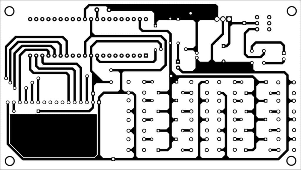
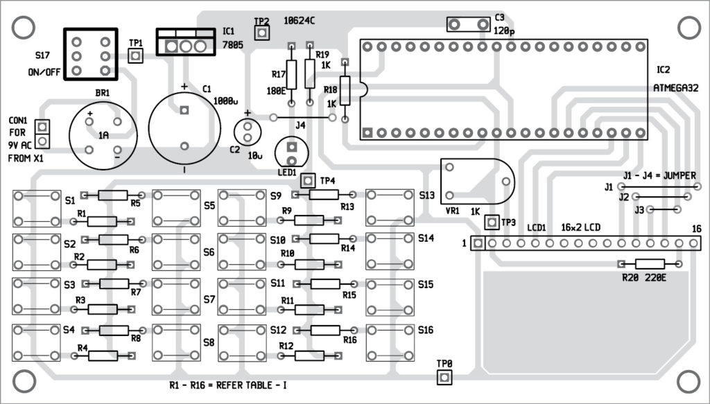
An actual-size PCB layout of the single-wire 4×4 keypad is shown in Fig. 3 and its components layout in Fig. 4. After assembling the circuit, enclose it in a suitable box.
Connect the secondary of transformer X1 to connector CON1 and primary to the AC mains via power cord. Mount LCD1 on the PCB and put the assembled PCB in a small cabinet. Fix switch S17 on the front side of the cabinet to switch on the circuit.
Download PCB and component layout PDFs: click here
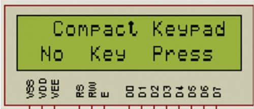
Testing is relatively simple and user-friendly. When you connect 9V power supply to the circuit via switch S17, LED1 glows, indicating the presence of power supply in the circuit. Wait for initialisation of LCD1 and microcontroller IC2. If everything is fine, you will see ‘No Key Press’ message on the LCD, as shown in Fig. 5.
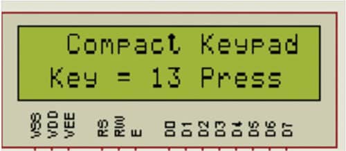
You can press any pushbutton. The corresponding value is displayed on the LCD. Fig. 6 shows the message on the LCD when pushbutton S13 is pressed.
First, check proper power supply at test point TP1 with respect to TP0. The voltmeter should read 9V-12V. Next, check the voltage at TP2, which should be 5V. If you don’t get 5V, either 7805 is faulty or there is some connection problem (short or open) in the circuit.
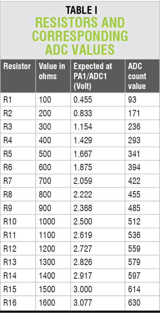
At TP3, check 5V supply for LCD1. Vary LCD1 contrast control by turning the preset (VR1) wiper right or left till you get text characters displayed on LCD1. Now, press switch S1 and check the voltage between TP4 and TP0. It shall be approx 0.455V. Repeat the same steps for all the keys by referring to Table I.
Nitin Kisan Khaire has many years of experience in product development and software validation. He has worked for engraving machine development using CPLD, FPGA and microcontrollers