


 The smart 230V AC bulb holder introduced here is an ultra-simple device with an automatic electric bulb controller switch and a standard electric bulb holder realised with the help of a few inexpensive and easily available components.
The electric bulb plugged into the integrated bulb holder of this fit-and-forget device wakes up at nightfall and ticks over just after the first light of day. The device can be used to drive an ordinary incandescent bulb, a light ballast (for fluorescent and discharge lamps), or a solid-state lighting fixture (CFL and LED bulbs) operating on a current less than or equal to 5A at 230V, 50Hz. The author’s prototype is shown in Fig. 1.
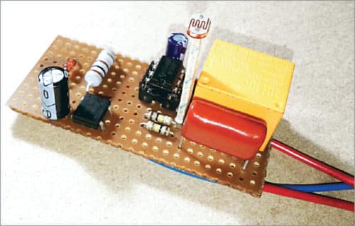
The circuit diagram of the smart bulb holder is shown in Fig. 2. It is built around a bridge rectifier (BR1), timer NE555 (IC2), optocoupler PC817(1), 12V Zener diode (ZD1), rectifier diode 1N4007(D1), 12V single-changeover relay (RL1), and a few other components.
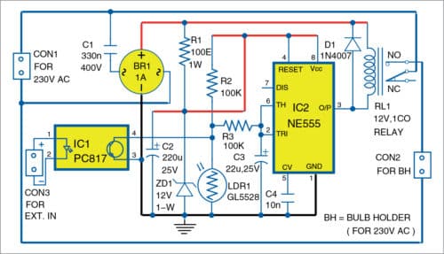
As you can see in the schematic diagram, the day/night sensor is a GL5528 light-dependent resistor (LDR), which forms a simple potential divider with an ordinary 100-kilo-ohm resistor (R2). The variable output voltage from this potential divider is used to control one G5L series (12V/400) electromagnetic relay (RL1) through an NE555 timer (IC2).
Note that when the input (pins 2 and 6) of IC2 is above 8V, the output (pin 3) goes low, and when the input is below 4V, the output goes high.
For controlling the bulb, common pole (P) and normally-open (NO) contacts of RL1 are used as a single-pole on/off switch to route AC input supply to the integrated bulb holder. Under normal conditions, RL1 is energised through IC1 when ambient light is less than ten lux. When light is greater than forty lux, it will de-energise the relay. You can alter the threshold level of LDR1 by changing the value of the resistor (R2).
The capacitive power supply is used here as the power source. It is configured to cater to a typical output current of 24mA. IC2 runs on about 12V DC supply available across the 220µF buffer capacitor (C2), while RL1 will get a DC supply of around 14.4V. This ‘elevated’ 14.4V ensures that RL1 will work smoothly even at the current level that is comparatively much lower than what is actually called for.
As you might notice in the diagram, there’s also a galvanically-isolated switch/sensor input in the device built around a common photocoupler PC817 (IC1). The option allows you to remove LDR1 and control the smart bulb holder from an external IoT (or similar) gadget if you desire to have a simple home automation project. It is to be noted here that if the photocoupler is in active state, the bulb will switch off. Needless to say, the photocoupler requires a current-limiter resistor at its input to set the typical forward current close to 20mA at 1.2V typical forward voltage.
Construction and testing
The entire circuit can be assembled on a rectangular piece of perforated or general-purpose PCB (refer author’s prototype). A PCB layout for the smart bulb holder is, however, shown in Fig. 3 and its components layout in Fig. 4. After assembling the circuit on the PCB, connect the 230V AC mains across CON1.
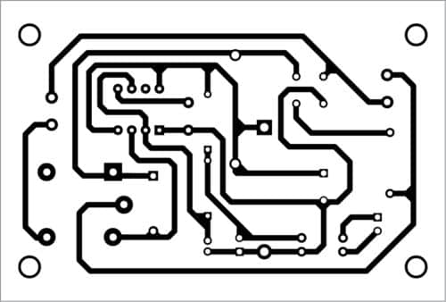

Download PCB and Component Layout PDFs: click here
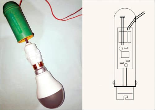
A small (waterproof) translucent enclosure is a must for this project. Prototype enclosures come in many shapes and sizes. It would be better to make your own enclosure if you’ve access to a 3D printer as it’ll give your model a polished look. A sample enclosure layout is also depicted here in Fig. 5 for your quick reference.
Author’s note
At first, the dimmable daylight LED bulb enclosed prototype was used for performance evaluation. Later, it was mounted on a garden lamp pole, and the real-world results (till now) are very promising. This smart bulb holder not only works as an energy-saving outdoor light bulb but also serves as a security light bulb or home occupancy indicator to deter prowlers even when you’re on a vacation.
Caution
This circuit involves the direct use of 230V AC mains voltage, which is dangerous, and the chances of getting an electric shock are high if not handled properly. If you are not used to handling such voltages, please get the help of a qualified person.
T.K. Hareendran is an electronics designer, hardware beta tester, technical author, and product reviewer. He is founder and promoter of TechNode.

today you new project i try it
thank you bro
You are most welcome.
What about using triac instead of relay
Will it be better or worse?
For incandacent bulbs, you can use TRIAC. For other loads like CFL, Discharge lamps, LED lamps etc…. you must use RELAY.
The author T.K. Hareendran replies:
Typical relays and triacs have virtually limitless applications. But this smart bulb holder circuit is designed to drive a relay, and the design math is optimised for that.
For a very high or unknown load, a relay is the most practical option. Relays work in a simple way—these can drive resistive, capacitive, and inductive loads at ease. Relays are perfectly isolated electromechanical devices and can work with AC and DC current, whereas triacs are semiconductor devices designed to control the distribution level of AC current, but without galvanic isolation. Besides, a triac has substantial voltage drop at useful current. A small inherent voltage drop is usually not a big issue when considering 230V AC operation, but the power dissipation can be.
Dear Sirs,
the download link for the PCB and Component Layout seems to be broken.
Please can you fix this?
Kind Regards
Mitsos
Please refresh the page and retry.