


As the hazards of mosquitoes are increasing day by day, the usage of electric liquid mosquito repellents is on the rise as well. These devices are widely employed for ensuring a good night’s sleep and are also commonly found in offices to enhance work environments.
Most liquid mosquito repellents are ruggedly constructed and operate continuously once activated.
But the continuous operation of these mosquito repellents causes the vapour content in the room to exponentially increase over time, which can cause harmful breathing effects and allergic reactions.

POC Video Tutorial In English
POC Video Tutorial In Hindi
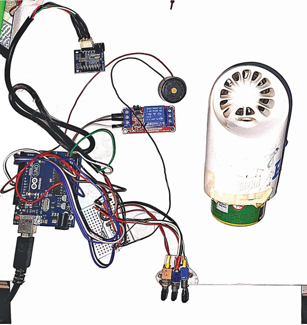
The smart timing operation for liquid mosquito repellents addresses this issue, offering different modes suitable for residential and office purposes. The author’s prototype is shown in Fig. 1, with the required components listed in Table 1.
| Table 1: Bill of Materials | |
| Components | Quantity |
| Arduino Uno board (MOD1) | 1 |
| DS1307 RTC module (MOD2) | 1 |
| One channel 5V relay module | 1 |
| 10-kilo-ohm resistor (R1, R2, R3) | 3 |
| On/off switch (S1 through S4) | 4 |
| 12V DC adaptor | 1 |
Liquid Mosquito Repellents Timer – Circuit and Working
The circuit diagram of the smart timer for liquid mosquito repellents is shown in Fig. 2. It is built around the Arduino Uno board (MOD1), RTC DS1307 module (MOD2), 5V relay module, 5V buzzer (B1), and a few other components.
The positive terminal of the buzzer (B1) is connected to pin D13 of the Arduino Uno, with its ground pin connected to the Arduino ground. A 12V DC adaptor that powers the circuit is directly connected to the DC socket on the Arduino Uno board.
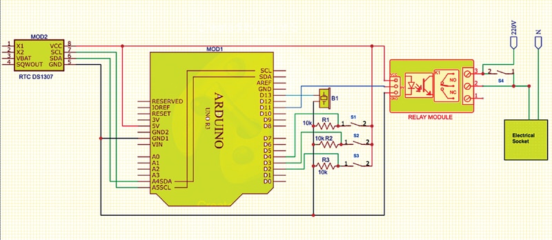
The relay’s normally-open (NO) pins are connected to a 220V AC, 6A electrical socket, which is also used to connect the liquid mosquito repellents.
An additional 6A SPST electrical switch (S4) is connected across the NO and COM pins of the relay module, which acts as a bypass switch whenever a smart switching action is not needed.
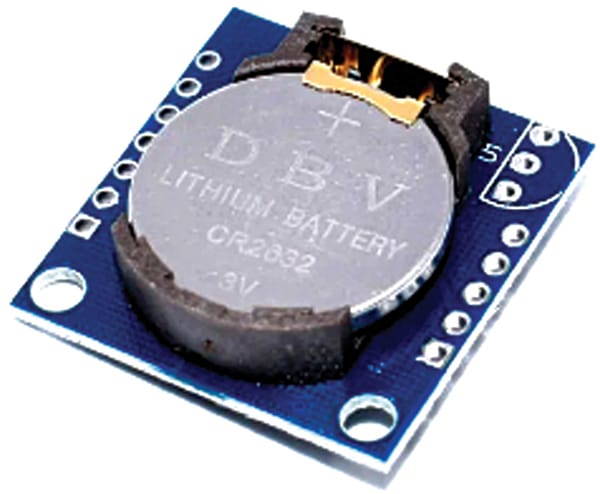
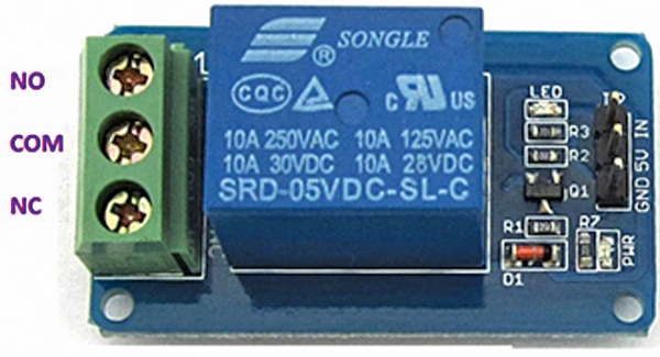
Images of the DS1307 I2C RTC module and the 5V relay module are given in Fig. 3 and Fig. 4, respectively.
The Arduino board, which is the heart of the system, is central to the real-time clock, mode selection switches, and the 5V relay board. The main purpose of the timer is to regulate the on/off cycles of the liquid mosquito repellent according to different modes of operation.
For convenience, it has seven modes that can be selected by three switches.
Mode 1: Night mode: In this general-purpose mode, the controller automatically switches on the mosquito repellent from 6:00 pm to 6:00 am for uninterrupted sleep. To enable this mode, keep switches S1, S2, and S3 open.
Mode 2: Night toggle mode: In this mode, the timer switches on the repellent continuously from 6:00 pm to 00:00 hours, then toggles from 00:00 hours to 6:00 pm, every hour. To enable this mode, close switch S1 and keep switches S2 and S3 open.
Mode 3: Night toggle mode with buzzer: It is similar to mode 2, but has an added feature of a buzzer acting as a wake-up alarm at 6:00 am. To enable this mode, close switch S2 and keep switches S1 and S3 open.
Mode 4: Office mode: In this mode, it operates continuously during office hours from 10:00 am to 6:00 pm, which is suitable for open office rooms. To enable this mode, close switches S1 and S2 and keep switch S3 open.
Mode 5: Office toggle mode: The repellent switches on and off hourly during office hours from 10:00 am to 6:00 pm, which is suitable for closed, air-conditioned office rooms. To enable this mode, close switch S3 and keep switches S1 and S2 open.
Mode 6: Hall mode: This mode is for use in halls during evening gatherings to keep the repellent switched on from 5:00 pm to 10:00 pm. To enable this mode, close switches S1 and S3 and keep switch S2 open.
Mode 7: All-day toggle mode: This mode operates the repellent continuously but non-sequentially, switching on and off every hour, which is ideal for office rooms operating 24/7. To enable this mode, keep switch S1 open and switches S2 and S3 closed.
The seven modes are controlled by push-to-on switches S1, S2, and S3, as shown in Fig. 1. These switches (S1 through S3) are simple on/off switches connected in series with the resistor between the 5V and the ground pin of the Arduino board.
Green boxes in Table 3 indicate the on-time of the liquid mosquito repellent. These switches are connected to the Arduino board pins as shown in Table 2. The positions of the switches and the corresponding modes of operation are shown in Table 3.
| Table 2: Arduino Uno pin connections with other components | |
| Arduino Uno Pins | Components such as RTC module, switches, buzzer, etc. |
| 5V pin | DS1307 I2C RTC module VCC pin |
| 5V pin | 2nd pins of S1, S2, S3 |
| 5V pin | Connected to VCC pin of relay module |
| Pin D2 | 1st pin of S3 |
| Pin D3 | 1st pin of S2 |
| Pin D4 | 1st pin of S1 |
| A4 | SDA pin of DS1307 I2C RTC module |
| A5 | SCL pin of DS1307 I2C RTC module |
| Pin D11 | Input signal pin of relay module |
| Pin D13 | Buzzer positive pin |
| GND | GND pin of relay module |
| GND | One end of resistors R1, R2, R3 |
| GND | GND pin of buzzer |
| GND | GND pin of DS1307 I2C RTC module |
| Table 3: Modes of operation | ||||||||||||||||||||||||||||
| TIME IN HOURS | 6 | 7 | 8 | 9 | 10 | 11 | 12 | 13 | 14 | 15 | 16 | 17 | 18 | 19 | 20 | 21 | 22 | 23 | 00 | 1 | 2 | 3 | 4 | 5 | ||||
| MSB | LSB | |||||||||||||||||||||||||||
| S3 | S2 | S1 | ||||||||||||||||||||||||||
| PIN 2 | PIN 3 | PIN 4 | MODE | |||||||||||||||||||||||||
| 0 | 0 | 0 | 1 | NIGHT MODE | ||||||||||||||||||||||||
| 0 | 0 | 1 | 2 | NIGHT SMART TOGGLE | ||||||||||||||||||||||||
| 0 | 1 | 0 | 3 | NIGHT SMART WITH BUZZER | BUZZER AT 05:59:55 sec | |||||||||||||||||||||||
| 0 | 1 | 1 | 4 | OFFICE MODE | ||||||||||||||||||||||||
| 1 | 0 | 0 | 5 | OFFICE TOGGLE | ||||||||||||||||||||||||
| 1 | 0 | 1 | 6 | HALL MODE | ||||||||||||||||||||||||
| 1 | 1 | 0 | 7 | ALL DAY TOGGLE MODE | ||||||||||||||||||||||||
Arduino Code for Liquid Mosquito Repellents Timer
The circuit operation is governed by the software program loaded into the internal memory of the Arduino Uno. The program, written in Arduino programming language, is uploaded using the Arduino IDE. The sketch initializes input and output pins and utilizes the wire library for communication with the DS1307 RTC module. Serial communication allows for monitoring of time and working mode.
The following functions and libraries are used.
Serial.begin(): Establishes serial communication between Arduino Uno board and another device, via a USB cable. It permits the two devices to communicate using a serial protocol. Here serial communication is used only to just read the data from Arduino Uno onto the screen. The displayed data allows us to know the time and working mode.
The following header files are used in the main code.
#include <Wire.h>: The Wire library allows to communicate through I2C devices, also called ‘2 wire’ or ‘TWI’ (two wire interface). The SDA (data line) and SCL (clock line) are used for communicating with the DS1307 RTC module.
#include “RTClib.h”: Used for communicating with the DS1307 RTC module. In the next step, initialize the relay pin as output.
Serial.begin(9600): Used for serial communication. For displaying the time on the serial screen, it is used for just reference purposes.
Two methods of setting the time into the RTC module
Method 1:
rtc.adjust(DateTime(F(__DATE__), F(__TIME__))); This line sets the time according to your computer time. It will set the present clock time of your system into the DS1307 I2C RTC module.
Method 2:
rtc.adjust(DateTime(2021, 7, 21, 10, 0, 0)); This command will set the time into the RTC module in this format (year, month, date, hours, minutes, seconds.) (for example: 2021, July, 21, 10:00:00 am). Once the time is set, the backup battery in the RTC module keeps the time for a long time.
Construction and Testing
Upload the source code into the Arduino Uno board, ensuring proper timing settings as indicated in the source code. Assemble the circuit on a breadboard and connect the 12V DC power adaptor to the barrel jack on the Arduino. Select modes using switches S1 through S3. The relay will energize and de-energize based on the selected modes, controlling the liquid mosquito repellent accordingly.
For manual operation or bypassing the circuit, remove the 12V power supply from the Arduino Uno board and use switch S4. Close switch S4 for manual activation and open it for manual deactivation of the liquid mosquito repellent.
K. Murali Krishna is working as a JTO, BSNL, 4G saturation project in Vishakapatnam. He is a technical enthusiast, writer, and an embedded systems and circuit designer
