


This smoke alarm built using a UM3562 sound generator can help maintain a smoke-free environment in apartments, offices, factories, restaurants, hospitals, etc. In this article, we’ll explore the working of this circuit and how to build it.
Fig. 1 shows the Smoke Alarm’s prototype while Fig. 2 shows the MQ2 sensor module used for the smoke alarm. The circuit diagram for the alarm is shown in Fig. 3.

Smoke Alarm Circuit
The circuit comprises a step-down transformer (X1), bridge rectifier (BR1), 5V voltage regulator LM7805 (IC1), MQ2 sensor module (connected across CON2), op-amp LM358 (IC2), sound generator UM3562 (IC3), three transistors (T1 through T3), an 8-ohm 0.5-watt loudspeaker (LS1), and several other components. Capacitor C1, connected across the supply terminals, minimizes voltage ripples and noise signals.


Working
The circuit works on 5V DC, which derives from the transformer X1. The 9V AC secondary of X1 connects to bridge rectifier BR1 for rectification, which then feeds the regulator LM7805 to obtain a stable 5V supply for the circuit. The glowing LED1 indicates the presence of smoke near the sensor module.
The heart of the circuit lies in the MQ2 smoke sensor module and the sound generator IC UM3562.
The smoke sensor module used here has three pins, but you can also opt for a four-pin module.
The output of the MQ2 sensor module is connected to pin 3 of IC2, while pin 2 is linked to potentiometer VR1 for sensitivity control.
IC2 serves as a comparator in the circuit. The output of IC2 connects to the base of transistor T1 via resistor R2 and also to the anode of LED1 through resistor R3.
The sound generator IC UM3562 (IC3) is a low-power CMOS LSI chip in an 8-pin dual in-line (DIP) package. It includes a voltage-controlled oscillator (VCO), timer generator, tri-state selector switch, envelope control, and mixer.
Pin 2 of IC3, along with trigger pin 4, functions as a tri-state selector switch, producing three types of sounds. In this design, we have not connected pin 2, so it is in a floating condition, generating the machine-gun sound.
IC3 operates on a 3V battery, so the 5V is reduced to the required level using transistor T1, resistor R4, and zener diode ZD1 (3.1V).
When the output of IC2 at its pin 1 goes high after sensing smoke from the sensor, UM3562 receives 3.1V at its Vcc pin, resulting in sound production.
Transistors T2 and T3 act as a Darlington pair to amplify the sound. Speaker LS1 produces the sound alarm to indicate the presence of smoke near the sensor.
The circuit’s working is simple. Normally, the sensor output is low when there is no smoke present.
However, when smoke is detected in front of the MQ2 sensor module, the sensor’s output goes high, enabling UM3562 via comparator IC2.
This, in turn, generates a machine-gun-like sound, alerting you to the presence of smoke.
When the sensor detects smoke, UM3562 produces the machine-gun sound alarm and, simultaneously LED1 lights up.
PCB Design
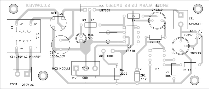
An actual-size, single-side PCB layout for the smoke alarm is shown in Fig. 4, and its component layout is shown in Fig. 5.

Assembly and Testing
After assembling the circuit on the PCB, enclose it in a suitable box. Fix LED1 and CON2 on the front of the box.
Connect the sensor’s three pins to CON2 using three different color flexible wires. Position the MQ2 sensor module to be exposed to maximum smoke during a mishap.
After assembling the circuit, install the unit at a suitable place, ensuring easy access by the sensor in the event of smoke production or excessive smoke in the area.
After properly installing the device at the venue to be protected, connect the sensor to the PCB of the assembled circuit. Now, your smoke alarm is ready to use.
EFY Note: This circuit uses a 3-pin MQ2 sensor module, but you can use a 4-pin MQ2 sensor module too. In that case, use output pin A0 and avoid pin D0.
Bonus: You can watch the below video tutorial for this DIY Smoke Alarm Project.
S.C. Dwivedi is an electronics enthusiast and circuit designer at EFY
