


 A mechanism that allows a machine to test itself is called built-in self-test (or BIST). It can generate patterns based on a variety of algorithms, each focused on a particular type of circuitry or fault type. Comparison function has a number of unique implementations including actual comparators as well as signal analysers.
In this project we will design Memory BIST (MBIST), which uses one or more algorithms specifically designed for testing memory faults. BIST structures generate patterns and compare output responses for a dedicated piece of circuitry. You can implement BIST on entire designs, design blocks or structures within design blocks. Pattern generation as well as output-comparison circuitry can vary depending on the design.
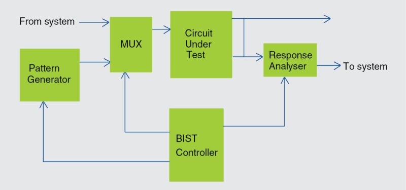
MBIST circuitry generates patterns and detects device failures. A basic MBIST block diagram is shown in Fig. 1.

BIST fault models
A manufacturing defect is a physical problem that occurs during the manufacturing process, causing device malfunctions of some kind. The purpose of test generation is to create a set of test patterns that detect as many manufacturing defects as possible.
The basic types of memory faults include stuck-at, transition, coupling and neighbourhood pattern-sensitive. In this project we will design BIST for memory stuck-at fault model, which means that a memory fails if one of its control signals or memory cells remains stuck at a particular value.
Stuck-at faults model this behaviour, where a signal or cell appears to be tied to power (stuck-at-1) or ground (stuck-at-0).
Device testing requires stimulus, a mechanism to apply stimulus to the device or circuit under test (CUT), and some means to analyse or compare the device’s responses with a known good (non-faulty) response.
Classical testing uses external test patterns as stimulus and applies the patterns to the device via a tester. The tester examines the device’s response, comparing it against the known good response stored as part of the test pattern data.
Fig. 1 shows how BIST places all these functions within the circuitry surrounding the CUT. A state machine is used to generate stimulus and analyse the response of the CUT.
BIST specifications. BIST is basically used to help in the testing of memory, which is an extremely complex architecture (fabrication wise), with the help of a few pins. In fact, while testing a memory using BIST, applying a simple clock signal along with a few pins helps test the entire memory IC.
Presented here is a BIST design using Verilog, which is simulated using ModelSim software.
Here, we design a memory model, BIST controller and its test bench, which is used to drive the entire operation of BIST. In bist_controller.v code, the finite-state machine is driven via a data generator, an address generator and a control generator. Also, MUX is used to select the operation of BIST or normal memory operations.
We design and analyse BIST using the pattern generator, which will write and read-back same patterns in all memory locations.
We considered 1024 inputs, each having 32-bit data. Now, for a functional test, a stuck-type fault model in logic circuits and their pattern generation for read-and-write operations will be demonstrated by writing a test bench for the memory model and BIST controller on ModelSim.
In this project we will test BIST for stuck-at-fault 0 for the memory model. The design hierarchy of BIST design is as follows:
• tb.v
• bist_controller.v
• memory_model.v
Here, test bench (tb.v) will generate a pattern for all memory locations with the help of a pattern generator defined in bist_controller.v, which will further generate the pass or fail status as per the finite-state machine.
You need to provide inputs manually to Memory_model.v when not in BIST mode. So, for testing of BIST for stuck-at-fault 0, we need to simulate the above-mentioned three files. Additionally, we need sim.do simulation file. It should be present in the same folder of the above-mentioned files.
Software program (Memory BIST)
Verilog programming is used in this project. Bottom-up design has been followed in this article in order to facilitate easy debugging of various modules.
Modelsim is an easy-to-use yet versatile VHDL/SystemVerilog/Verilog/SystemC simulator from Mentor Graphics. It supports behavioural, register-transfer-level and gate-level modelling.
To start BIST design and memory model simulation, install ModelSim V10.4a on a Windows PC and follow the steps mentioned below:
Create the project. (Memory BIST)
1. Start ModelSim from the desktop; you will see ModelSim 10.4a dialogue window.
2. Create a project by clicking Jump Start on Welcome screen.
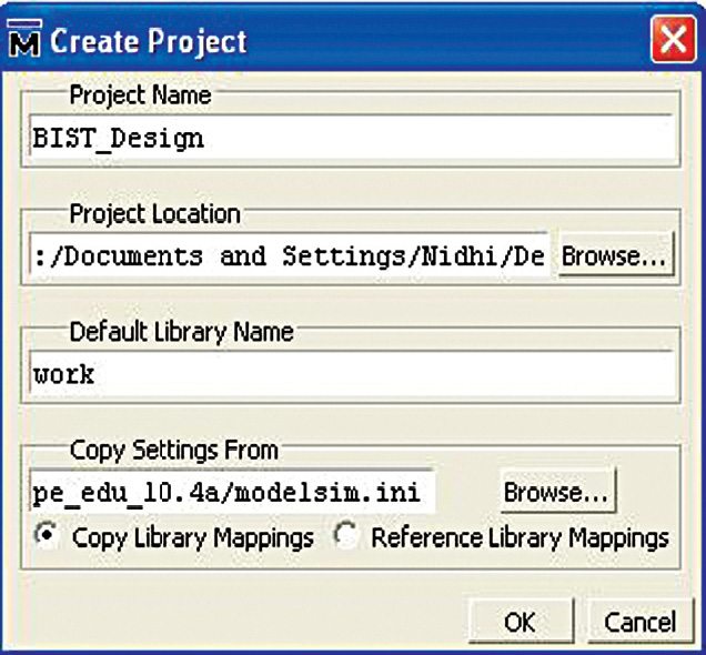
3. Create Project window pops up (Fig. 2). Select a suitable name for your project. Set Project Location to C:/Documents and Settings/Nidhi/Desktop/Final_BIST (in our case) and leave the rest as default, followed by clicking OK.
4. Add Items to the Project window pop up (Fig. 3).
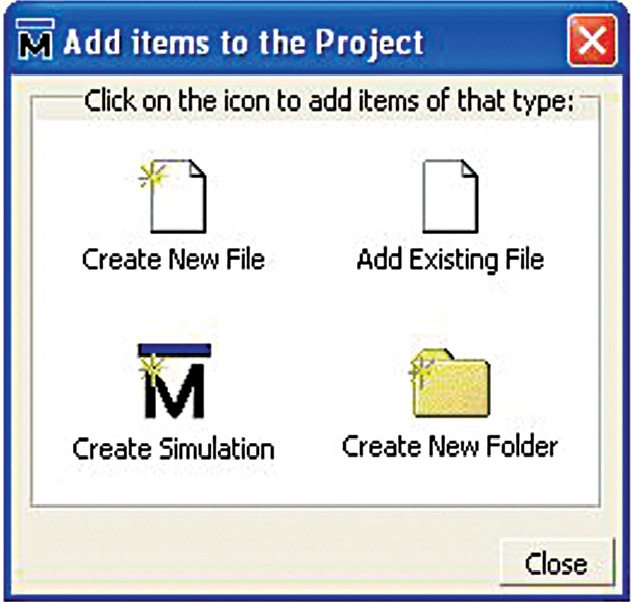
5. On this window, select Create New File option.
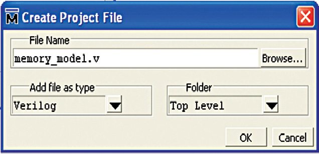
6. Create Project File window pops up. Give an appropriate file name (say, memory_model.v) for the file you want to add, and choose Verilog as Add File as Type and Top Level as Folder (Fig. 4).
7. On the workspace section of the main window (Fig. 5), double-click on the file you have created (memory model.v in our case).
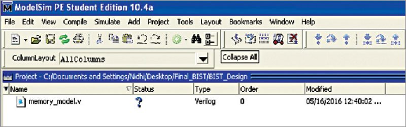
8. Type your Verilog code (memory_model.v) in the new window. Here we have considered 1024 inputs, so we write first data as 32’h42_40_40_40. Note that, these inputs are arbitrary and so you can enter any 32-bit data. Our goal is to obtain the same data back. Here, we test the memory manually and verify the BIST operation of a memory model using test bench and BIST controller.
In this example, we first write data as 1s in all memory locations. Then we read back all locations. We expect all the read data to be 1s in the result. If there is even a single 0 in the result, that means some cell or bit is stuck-at fault 0. There exists a fault and so BIST test has failed. This is achieved by ANDing all bits.
9. Save your code from File menu.
10. Add relevant Verilog source files that actually test the BIST operation of a memory. These include memory model, BIST controller and a test bench, which will then check the output for each input.
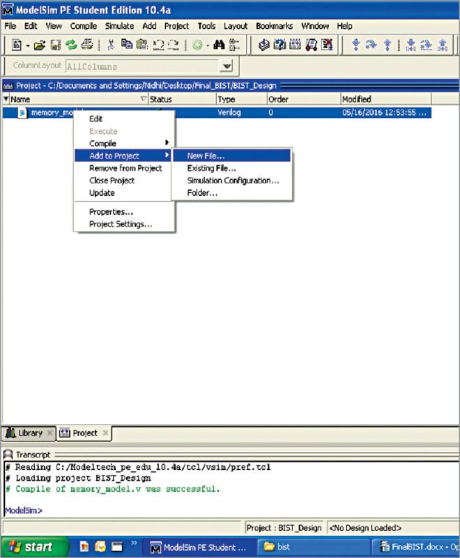
Add new files to BIST project by right-clicking memory model.v file.
Select Add to Project->New File option as shown in Fig. 6.
Give File Name bist_controller.v and follow the steps from 7 through 9 as mentioned above.
Similarly, add test bench file (tb.v) to the project and enter respective Verilog codes in these files.
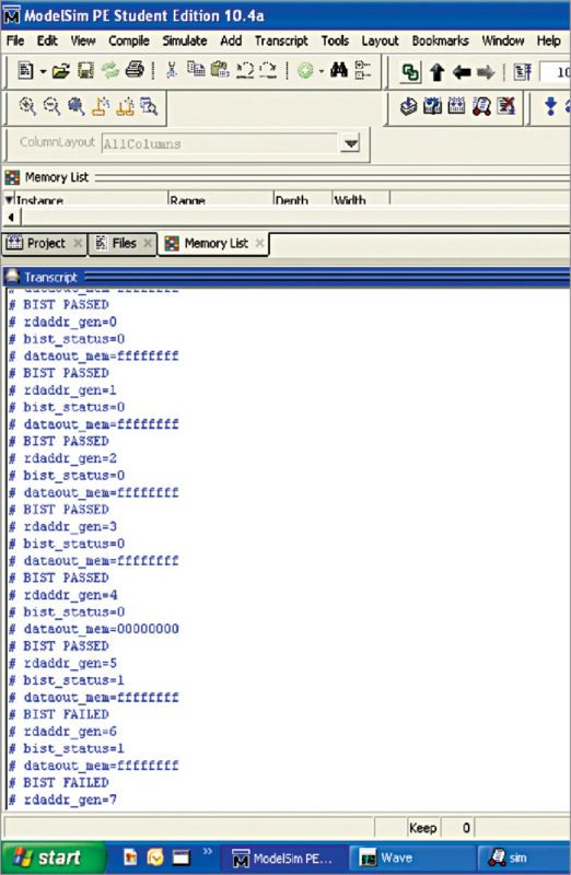
The test bench should indicate bist_status 0 and bist_status 1 for BIST passed and BIST failed, respectively.
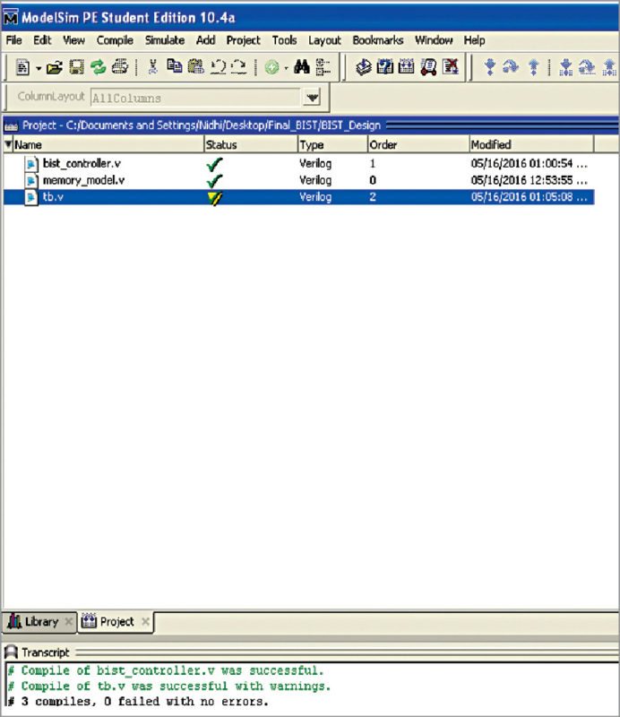
The final workspace window is shown in Fig. 7.
Compiling/debugging project files.
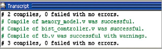
1. Select Compile->Compile All option.
2. Compilation result is shown on the main window. A green tick is shown against each file name, which means there are no errors in the project (Fig. 8).
Simulating BIST design
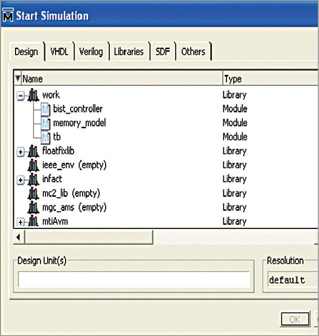
1. Click on Library menu from the main window and click on plus (+) sign next to the work library. You should see memory_model, bist_controller and tb that we have just compiled (Fig. 9).
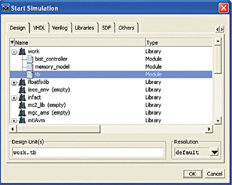
2. Now, in the work library, select tb and click OK (Fig. 10). This will open sim default window as shown in Fig. 11.
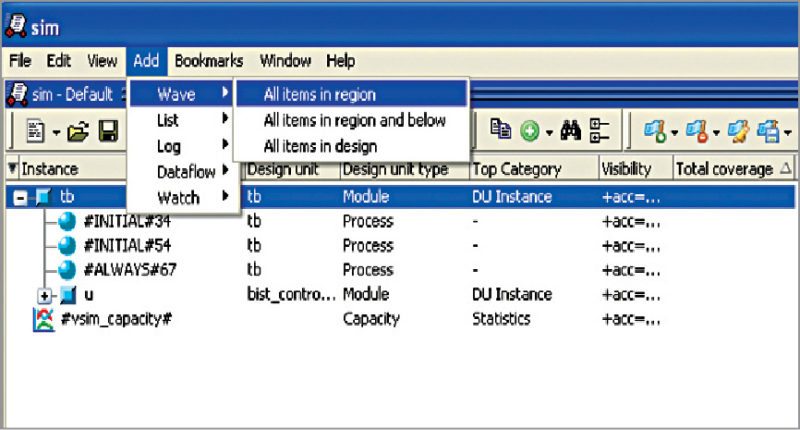
3. Go to Add->To Wave->All items in design options.
4. Select the signals that you want to monitor for simulation purposes. This is a test bench, so it will write something using the pattern generator and read back the same pattern automatically.
This is the main concept of BIST. No external inputs are required when the memory model is in BIST mode.
We are now ready to simulate by writing do sim.do command in the transcript window (Fig. 12). Now, click Enter; you should be able to see the output being displayed on the console (transcript window). BIST captures the pass or fail status in this result window (Fig. 13).
To observe stuck-at fault 0, we intentionally forced a memory location to invert input data in the example (refer tb.v for the same). Once a fault is detected, BIST will indicate as failed in the result even if there is no fault in the remaining memory locations.
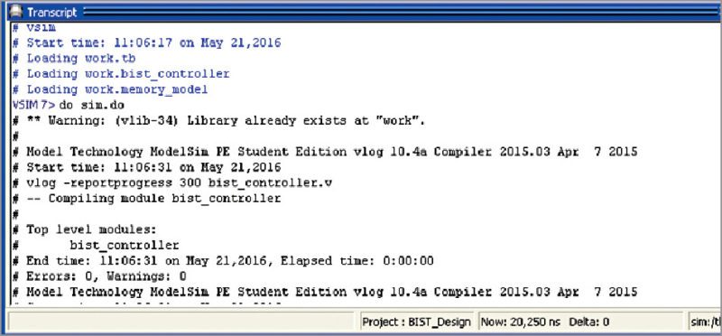
Thus, the result of BIST design is verified from the transcript window as shown in Fig. 13.
This project on BIST for stuck-at-fault has been verified by Nithin Kumar Guggilla, manager at Xilinx India. He says, “Since FPGAs can be programmed with any design on the fly, if needed, designers can implement their own BIST using pseudo-random or pre-calculated generators and signature in their RTL. This would be implemented in look-up tables and flip-flops, which will create some overhead in addition to the actual resources needed for the design.”
Xilinx FPGAs also provide dedicated memory that can be used in various applications. There is a built-in error-correction capability for Xilinx block RAMs. Each block RAM has an error-correcting code circuitry associated with it. This can be enabled to correct single-bit errors and detect double-bit errors. So, effectively, Xilinx FPGAs have both BIST as well as built-in self-repair (BISR), where repair can be done for a single bit.
Among the various modes (single port, simple dual port and true dual port) supported by block RAM, error-correcting code is supported in simple dual-port mode. In this mode, the block RAM can be configured as 512 x 64 RAM. The extra eight bits in the 72-bit wide RAM are used towards built-in Hamming code-error correction.
Download source code: click here
Sample code. If you want to use error-correcting code facility of Xilnx BRAM, set the corresponding parameters/ports during instantiation, as shown in the following Verilog example:
[stextbox id=”grey”]ramb36e2 #(
.…
.en_ecc_pipe(“true”),// enabled
pipeline on ecc, for higher
performance
.en_ecc_read(“true”), // enabled ecc
for read
.en_ecc_write(“true”),// enabled ecc
for write
….
.read_width_a(72),// read width port
a – 72 in sdp mode
.write_width_a(0),
.write_width_b(72)) // write width
port b – 72 in sdp mode
mem_reg
(
// other ports
……….
.eccpipece(1’b1), // to enable ecc
pipelines, connect enable or 1
.casoutsbiterr(), // use in
cascade mode
.casoutdbiterr(), // use in
cascade mode
.sbiterr(sbiterr), // single bit
error status
.dbiterr(dbiterr), // double bit
error status
.eccparity(eccparity) // parity bits
);[/stextbox]
If you like this DIY, you may also like FIFO Design Using Verilog
Nidhi Kathuria is a senior application engineer at EFY Tech Center, New Delhi

Hello sir I want to contact the author of this article that is Nithin Kumar Guggilla for further assistance in my project.So can you please share your mail ID it would be a great help.
Looking ahead for your reply
Thank you
hello sir, ive tried this tutorial using modelsim 10.4 student edition and my problem now is this error shows up “# Cannot open macro file: sim.do” when i wrote “do sim.do” for simulation. Any solution sir ?
Hello sir, I cannot simulate this code in Modelsim, it shows some error. Can you please give alternatives or help?
Dear Sir, i also want to contact the expert in BIST memory testing for my project.
thanking you.
not able to download codes.
Please refresh the page and retry.