


 This project can be used in the laboratories of industrial training institutes (ITIs), polytechnics, and engineering colleges to study the half-wave and full-wave rectifier waveforms using an Arduino Uno. While electrical power from the mains supply is available as AC, almost all electronic equipment use DC power supply.

[signinlocker id=”87626″]
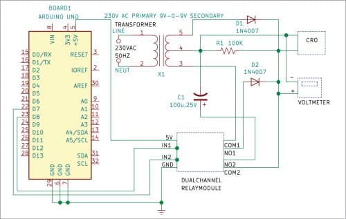
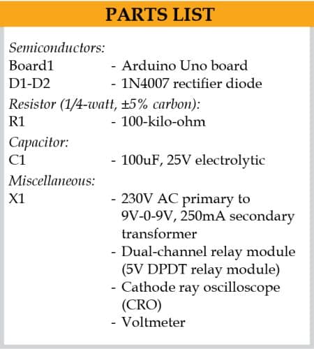
Arduino Uno’s digital pins 8 and 7 are connected to input pins IN1 and IN2 of the dual-channel relay module, respectively. Common (COM1) and normally open (NO1) terminals of the relay are connected to transformer’s secondary terminal and anode of diode D2, respectively. NO2 terminal of the relay is connected to positive terminal of electrolytic capacitor C1 and COM2 terminal of the relay is connected to the junction of cathodes of diodes D1and D2 and resistor R1. Negative terminal of capacitor C1 is connected to centre-tap on secondary side of the transformer. The output waveform can be observed on an oscilloscope connected across resistor R1.

The centre-tap transformer is used to step down the supply voltage from 230V to 9V-0-9V. The two 1N4007 diodes (D1 and D2) and 100µF, 25V electrolytic capacitor (C1) are used to get different output waveforms.
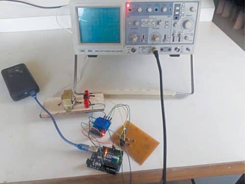
Construction and testing
Solder all the components on a Veroboard and upload the source code (Study.ino) on Arduino Uno board using Arduino IDE. Place the CRO probes across resistor R1.
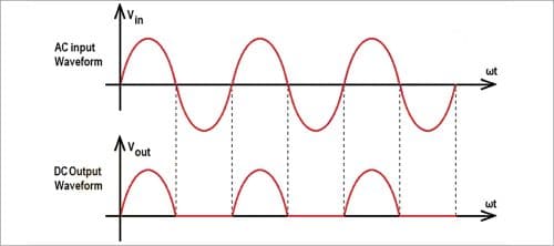
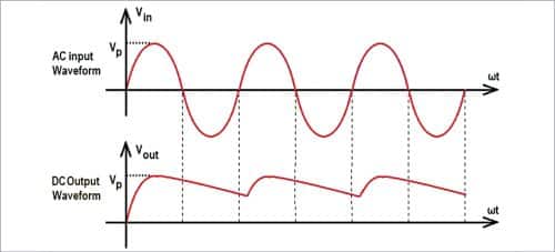
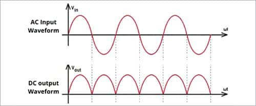

When the circuit is switched on, you get half-wave output without filter capacitor C1, as shown in Fig. 3. Next, the program automatically outputs half-wave output, as shown in Fig. 4. This is followed by full-wave output without filter, as shown in Fig. 5, and full-wave output with filter, as shown in Fig. 6. The program keeps repeating in this sequence to output different waveforms.
Download Source Code
As can be seen from Fig. 3 through Fig. 6, the waveforms available include the input and output voltages for comparison. The DC output obtained from pulsating DC input can be smoothened by increasing the value of filter capacitor C1. You can also connect a voltmeter across the diodes and centre-tap of transformer to measure the output voltage.
Vinaya Kumar K. is an instructor in EEE Department of NIE Institute of Technology, Mysuru (Karnataka)
[/signinlocker]

