


This FM radio receiver project demonstrates the practical application of RF engineering and analog signal processing principles. Designed to operate within the standard Very High Frequency (VHF) band of 88 to 108 MHz, the system effectively captures, isolates, demodulates, and amplifies Frequency Modulation (FM) signals.
By leveraging frequency modulation rather than amplitude variation, the receiver inherently rejects common atmospheric and electrical noise to deliver high-fidelity audio output.
POC Video Tutorial
This FM radio receiver circuit is designed using the TDA7000 FM receiver IC to receive broadcast signals in the VHF FM band. The project demonstrates how frequency-modulated (FM) signals can be received, demodulated, and converted into audible audio output using a compact integrated circuit solution.

Unlike complex superheterodyne receivers, the TDA7000 IC integrates RF tuning, intermediate frequency (IF) processing, demodulation, and muting functions within a single chip, making it ideal for simple and low-cost FM radio designs.
The circuit is built on a breadboard and powered using a regulated 5V supply derived from a 9V battery through an L7805CV voltage regulator to prevent FM signal interfaring with external noise.
The project highlights key concepts such as RF tuning, frequency demodulation, signal filtering, and audio amplification in practical radio communication systems.
| Parts List |
| Semiconductors IC1 – L7805 Voltage Regulator IC IC2 – TDA7000 FM IC IC3 – LM386 Audio Amplifier IC Resistors (all ¼-watt, 5% carbon film) R1 – 74Ω R2 – 10kΩ R3 – 22kΩ VR1 – 10kΩ preset Capacitors C1,C2,C19 – 10µF, 25V electrolytic capacitor C3,C6 – 10nF ceramic disc capacitor C4 – 150nF ceramic disc capacitor C5 – 22nF ceramic disc capacitor C7,C10 – 3.3nF ceramic disc capacitor C8 – 180pF ceramic disc capacitor C9,C15 – 330pF ceramic disc capacitor C11 – 150pF ceramic disc capacitor C12,C13,C16 – 220pF ceramic disc capacitor C14,C18 – 100nF ceramic disc capacitor C17 – 1.8nF film capacitor C20 – 220µF, 25V electrolytic capacitor Cv – trimmer capacitor (20pF-40pF) Cs – 2pF to 22pF ceramic disc capacitor Cp – 22pF to 40pF ceramic disc capacitor Inductors L1 – 4 turn, 22 SWG, 5mm diameter (80nH-100nH) Miscellaneous AE1 – Antenna BT1 – 9V battery S1A – on/off switch LS1 – 8Ω speaker – General-purpose PCB/breadboard – Connecting/jumper wires – Enclosure (optional) |
Make sure to buy these components from trusted sellers. The EFY team has researched and listed verified online electronics component suppliers.
FM Radio Receiver Circuit and Working
The circuit diagram is shown in Fig. 1. The FM receiver circuit is built around the TDA7000 IC, along with a few passive components for tuning, filtering, and stabilization. The output of the TDA7000 IC is fed into the LM386 audio amplifier to make the audio frequency signal into a hearable sound.
A 9V battery (BT1) is used as the primary power source. The voltage is regulated to 5V using the L7805 voltage regulator(IC1), ensuring stable operation of the IC. Capacitors are used at the input and output of the regulator to filter noise and maintain voltage stability.
An antenna (U1) is connected to the RF input of the TDA7000 (IC2) to capture FM signals from nearby broadcast stations. The tuning circuit, consisting of an inductor(L1) and a variable capacitor (CV), selects the desired frequency within the FM band. By adjusting the tuning capacitor, different radio stations can be received.
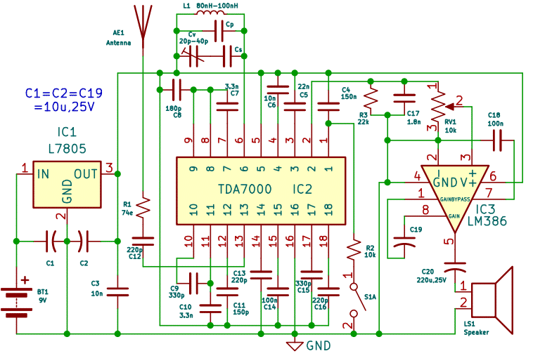
The TDA7000(IC2) internally converts the received RF signal into a low intermediate frequency (IF) signal. It then demodulates the FM signal to extract the original audio signal.
The demodulated audio signal is available at the output (pin 2) of the IC2. This signal is then fed into an LM386 audio amplifier for driving a speaker.
The IC2 includes an internal muting circuit (at pin 1) that suppresses noise when no valid station is tuned, improving listening quality.
Construction and Testing
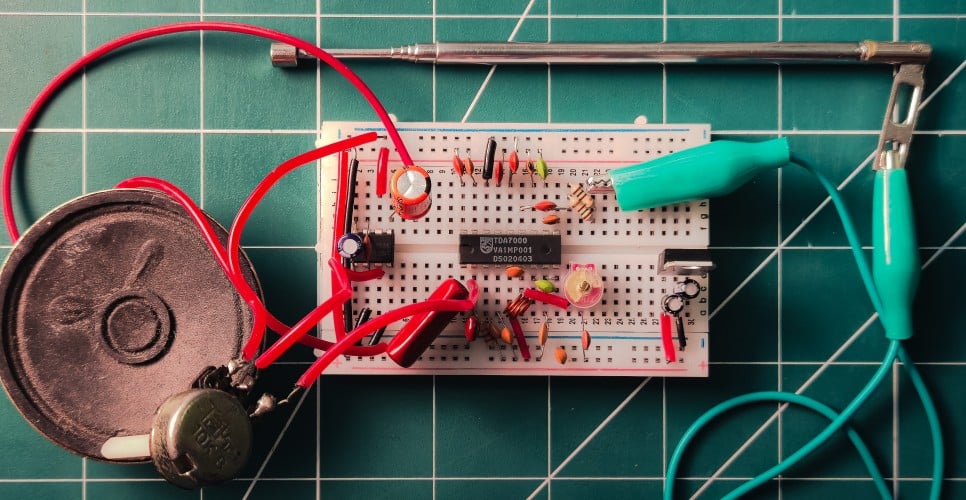
The entire circuit is assembled on a breadboard for easy prototyping and modification, as shown in Fig. 2. But there are a few things to keep in mind for breadboard prototyping:
- Ensure short and proper wiring to minimise noise interference.
- Keep antenna wire properly extended and test the prototype in an open space for better reception.
- Place decoupling capacitors as close to the IC as possible to reduce interference.
- Use a proper ground connection for stability.
For testing, a 9V battery(BT1) is connected to the voltage regulator(IC1), then the 5V output is verified and fed into both TDA7000(IC2) and LM386(IC3). Now the output of TDA7000 is connected to the amplifier, and volume can be adjusted with the 10k potentiometer(RV1).
The inductor(L1) is made with a 4-turn 22 SWG copper wire at 5mm diameter. Now, slowly adjust the variable capacitor(CV) with a screwdriver for tuning. If required, the inductor windings can be adjusted(pushed or pulled) for tuning the circuit. Various stations can be heard by adjusting the variable capacitor.
A 10uF, 25V capacitor(C19) is placed between pin 1 and pin 8 of LM386 for maximising the gain to 200. Also, a 100nF capacitor(C18) is added between pin 7 and pin 2 for more stability and noise filtering for driving the speaker.
What if the signal is not received?
The signal reception is fully dependent on the tuning circuit after the antenna stage. A limiter circuit can be added to address this issue, in which a capacitor(CP) is placed in parallel, and another capacitor (CS) is placed in series with the variable capacitor. This creates a “pass band” for frequency to be tunable within the FM band. But this “pass band” depends on the CP and CS. CP could be around 22pF to 40pF, and CS could be around 2pF to 22pF according to the stray capacitance and inductance from breadboard rails, so this needs to be carefully selected and tuned.
The actual size PCB of the receiver is shown in Fig. 3, and its components layout in Fig. 4.
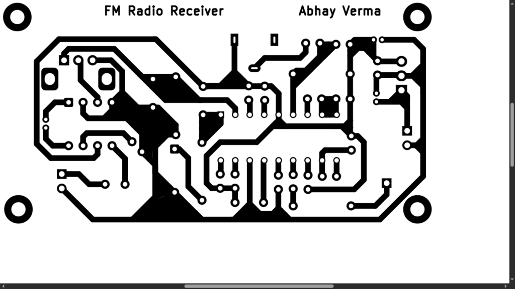
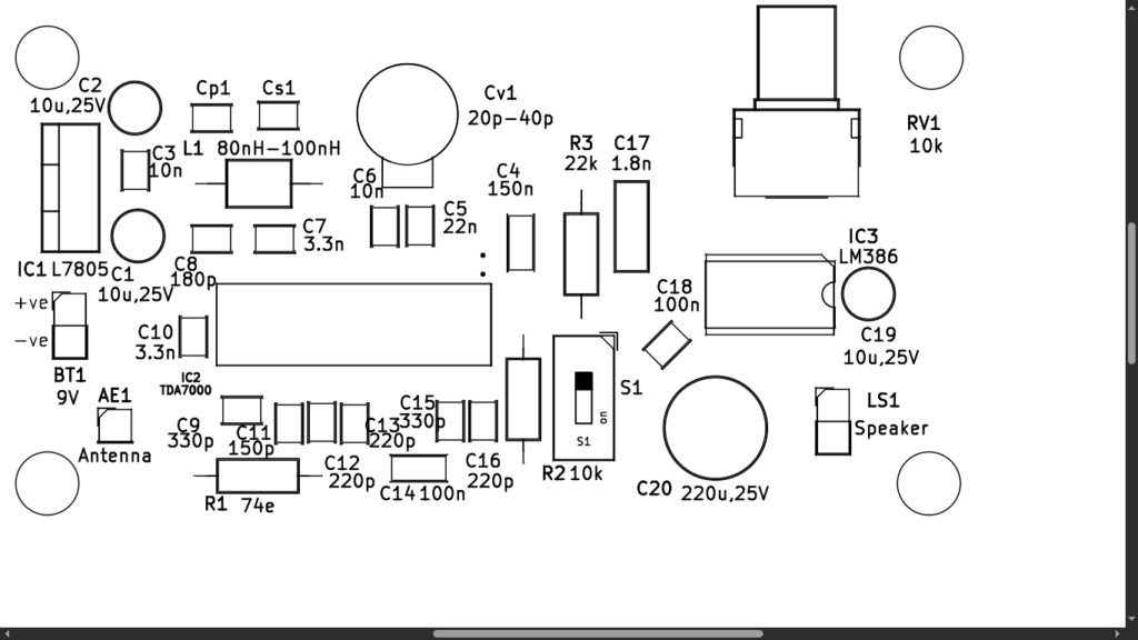
Download PCB and Components Layout PDFs: click here
Download TDA7000 Datasheet
Video Tutorial
Learning Points
This project provides a clear understanding of how frequency-modulated (FM) signals can be received and converted into audible sound using a compact integrated solution like the TDA7000.
The project also emphasises the importance of proper voltage regulation using components like the L7805CV, ensuring stable operation and accurate frequency tuning in sensitive RF circuits. The inclusion of an external audio amplification stage, typically using an IC such as the LM386, provides insight into low-power audio signal amplification. The weak demodulated audio output from the TDA7000 is boosted by the amplifier to a level sufficient to drive a speaker, illustrating the practical need for impedance matching and signal conditioning between stages.
The project also highlights real-world challenges such as noise reduction, proper grounding, and minimising interference in breadboard implementations.
Overall, this project offers a strong foundation in RF electronics, analogue signal processing, and hardware integration, showing how multiple stages—from RF reception to audio output—work together to form a complete FM radio receiver system.
“Now take an IC1 TA 2003 and place it on an 8-pin IC socket.”
It should be 16-pin IC socket and not 8-pin IC socket.
Sir,
In the parts list C5 mentioned as
C5: 0.01uF
But I can’t locate C5 in the schematic or layout.
Thanks for detecting this error and sharing with us.
Regards