


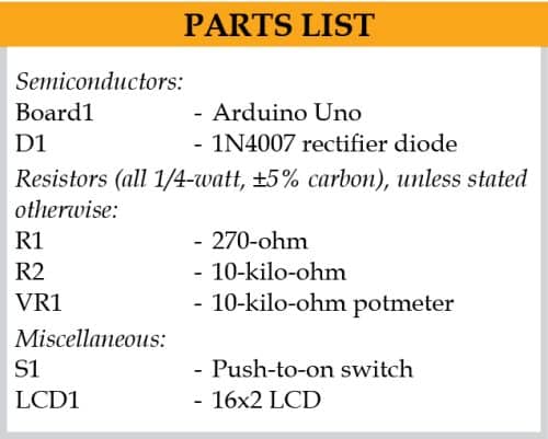
 A taxi meter in cabs and autorickshaws calculates the fare based on the distance travelled. Here is a circuit that calculates the trip fare based on the rate per km and displays the distance travelled and the total fare.
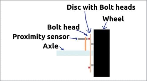
The circuit (see Fig. 1) comprises Arduino Uno Board1, 16×2 LCD display LCD1, and inductive proximity sensor connected across CON2. A metal target such as a bolt-head required by the sensor for proper functioning is fixed on the rotating object such as a wheel’s rim or a wheelnut to sense the rotation.
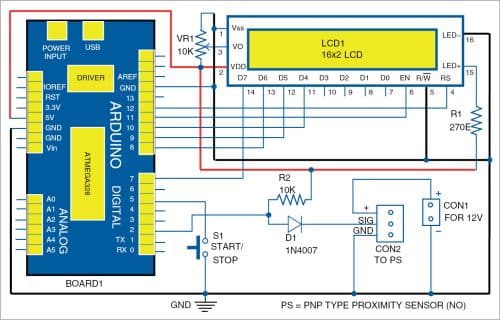
Whenever the metal target crosses the sensor while rotating, the sensor generates a pulse. The pulse goes to the first interrupt pin (pin 2) of the Arduino through diode D1. The diode acts as a voltage level converter. Since the proximity sensor’s working voltage is 12V, its output pulse voltage is 0-12V.

The Arduino cannot withstand 12V voltage, so the diode is used to change it to 5V logic pulse for the Arduino. If the sensor output is high, the diode does not conduct and the 5V is available at pin 2 of the Arduino through pull-up resistor R2. If the sensor output is low, the diode gets forward biased and pulls pin 2 to ground, thus providing logic low at pin 2 of Board1.
The Arduino counts the number of pulses for one rotation of the wheel and converts to distance in kilometre (km) through the program. The distance is then multiplied with the rate per km to get trip fare for the distance travelled. LCD1 displays the distance and trip fare.
On completion of the trip, the total fare displayed on LCD1 is noted and switch S1 is pressed again to register completion of the trip. Now LCD1 displays “TRIP COMPLETED, THANK YOU” for one second and then displays the first message again for the next trip.
PNP type normally-open (NO) proximity sensor used in the circuit (see Fig. 2) detects objects without any physical contact up to its nominal range—the maximum distance that this sensor can detect. It has high reliability and long functional life because of the absence of mechanical parts and lack of physical contact between sensor and the sensed objects.

Construction and testing
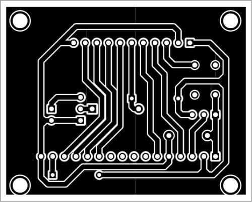
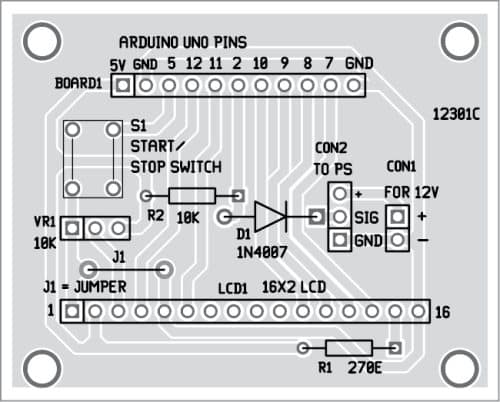
A single-side PCB layout shown in Fig. 3 can be used for the circuit. Its component layout is shown in Fig. 4. Assemble the circuit on PCB and connect 12V and Gnd across CON1 and proximity sensor across CON2. Switch S1 is used to stop/start the circuit. After assembling the circuit enclose it in a suitable enclosure.
Download PCB and Component Layout PDFs: click here
The program is written in Arduino programming language (sketch). Arduino IDE is used to compile and upload the program to the Arduino board. Select the correct board from BoardTools menu in Arduino IDE, select COM port and upload the program through the standard USB port in computer.
Please note the following:
- Most cabs (especially autos) have 40.6cm (16-inch) dia tyres, which means their circumference is approximately 128cm (0.00128km). So, with each rotation of the wheel the distance travelled is 0.00128km.
- In this project, the cost per km is set at ₹ 9, but it can be changed in the program.
- More than one metal target can be used to get better resolution of the distance travelled. During testing, five targets were used.
- A pull-up or pull-down resistor may be required at output of the sensor, depending on the type of sensor used.
- A proximity sensor with nominal range of 5 to 10mm can be used.
- An opto-slotted IR-photodiode pair with slotted disc (see Figs 5 and 6) can be used for sensing the rotation in place of the proximity sensor.
- The disc should be fixed at the inner side of the wheel as shown in Fig. 7.


A. Samiuddhin, a circuit designer, is B.Tech in electrical and electronics engineering. His interests include LED lighting, power electronics, microcontrollers, and Arduino programming
