


 This simple temperature controlled circuit triggers automatically when the ambient temperature goes beyond a set limit of, say, 50 degrees centigrade. This temperature setting can be changed as per requirement through the potentiometer in the circuit.
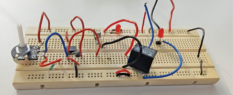
The circuit has three parts: the sensor, main control unit, and relay driver. It works on 230V AC mains. A bulb used in the circuit acts as a load for demonstration purpose. When the room temperature goes beyond the set limit the bulb switches on automatically. The author’s prototype is shown in Fig. 1.
Watch the full Video Tutorial below:
Circuit and working
Circuit diagram of the temperature controlled switch is shown in Fig. 2. The circuit comprises step-down transformer X1, bridge rectifier BR1, 5V voltage regulator 7805 (IC1), temperature sensor LM35 (IC2), op-amp LM35 (IC3), 5V single changeover relay RL1, and a few other components. Capacitor C1 connected across the supply terminals minimises any ripples or noise signals in the voltage.

The circuit needs 5V DC to operate, which is derived from the 9V, 500mA secondary side of transformer X1. The 230V AC mains is connected to the primary of X1 via CON1 in the circuit whose 9V AC secondary is connected to bridge rectifier BR1 for rectification. The rectified and filtered voltage (by C1) is given to IC LM7805 to get regulated 5V for the circuit. Glowing of LED1 indicates that 5V is being supplied to the circuit.
The IC LM35, heart of the circuit, is a 3-pin device like a transistor with pins for VCC, GND, and OUTPUT. It gives variable voltage at the output based on temperature up to 150 degrees Celsius. This popular and inexpensive temperature sensor is generally used in digital thermometers.
For every one degree centigrade rise in temperature there is 10mV increase in voltage at the output pin. Let us say, at 0°C the output of sensor is 0V. When the temperature rises to 10°C the output will become 100mV; at 25°C it will become 250mV.
Temperature sensor LM35 senses the temperature and gives the signal to the controller built around IC LM358. The data received by the controller is then given to relay driver circuit built around driver transistor T1 and relay RL1. On receiving the signal from the controller, the relay is tuned on/off. This process repeats forever.
Calibration of LM35 sensor should be done as we have used op-amp LM358 to compare the output voltage of LM35 with the reference voltage. Since the circuit has been set for threshold voltage of 50°C, to trigger the op-amp we need to set the reference voltage to 0.5V, as at 50°C the output of LM35 will be 0.5V. The reference voltage is at pin 2 of LM358.
Working of the circuit is simple. When power is switched on, LED1 glows and the circuit is ready to use. As soon as some heat is provided near LM35 sensor, the temperature at pin 3 of IC3 goes higher than the reference voltage at pin 2, so the output of op-amp IC3 at its pin 1 goes high and relay RL1 energises. As a result, the light bulb gets disconnected from the 230V AC supply and switches off.
When temperature at pin 3 of IC3 goes lower than the reference voltage at pin 2, the output of op-amp IC3 at its pin 1 goes low and relay RL1 de-energises. As a result, the light bulb gets connected to 230V AC and switches on.
