 This GPS-based project displays analogue clock and room temperature on a TFT display. GPS time is a precise time standard that is related to Coordinated Universal Time (UTC). The displays of most electronic hobby projects are based on LCD, GLCD, OLED or TFT. This project is based on an 8.89cm (3.5-inch) TFT display having 480×360 pixel resolution (Fig. 1).
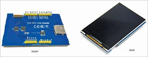
The latest Chinese TFT displays are quite low in price but work perfectly with Arduino and Raspberry Pi. There are two different types of TFT shields available: one with 26 pins (13×2 DIL) for Raspberry Pi and the other as Arduino TFT shield for Arduino Uno board.
Arduino TFT shield
Arduino TFT shield can be perfectly mounted on top of an Arduino Uno board. But a major disadvantage is that after mounting the shield on Arduino Uno board, it is difficult to use its GPIO pins for any other application.
The Arduino TFT shield has a micro SD card attached that gets connected to its serial peripheral interface (SPI) pins for communication with the microcontroller. This micro SD card is not used in this project.
The main hurdle with this display is that it is not common and is available only from mcufriend.com. Fortunately, the mcufriend_kbd.h header file is freely available and it works out of the box for this and many other similar displays. The other header file required for this display is Adafruit_GFX.h. Both these header files, along with the main source code, are given below.
This project creates an analogue dial clock along with digital date, time and temperature display using an LM35/TMP36 temperature sensor. The time signal is derived from a U-Blox NEO-6M GPS receiver module. Once the technique is understood, it can be deployed for many other applications.
Construction
The project for the GPS analogue clock with temperature display requires the following components:
- 8.89cm TFT shield
- Arduino Uno
- U-Blox NEO-6M GPS receiver
- LM35/TMP36 temperature sensor
- 3.3V DC regulator/power supply
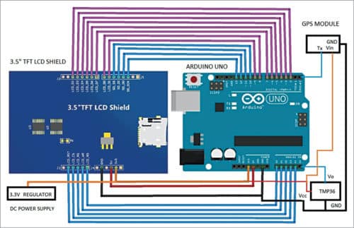
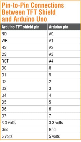
The connections are easy to make as shown in Fig. 2. The pin connections of the Arduino TFT shield are straightforward; you just need to mount the shield on top of the Arduino Uno board. The pin-to-pin connection details between TFT shield and Arduino Uno are given in the table.
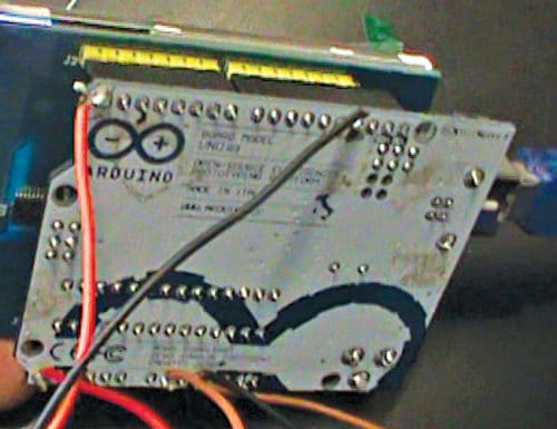
Since top portion of the Arduino Uno is covered by TFT shield, the connections for the TMP36 and GPS receiver are taken from the bottom side of the Arduino Uno board (refer Fig. 3). In case you want to free some Arduino pins then you should see the mcufriend_shield.h file and re-write the connections to do so.
The shield is basically for 3.3V operation, but may work up to 5V. However, prolonged operation on 5V is not recommended as it gets overheated at that voltage. The 3.3V supply is derived from an LD1117V33 voltage regulator.
Software
Writing the Arduino code/sketch (GPS_analog_clock.ino) for the project is real fun! You can make TFT display in many different ways through coding. Creating a thick border line, making the hour and minutes hands move smoothly were quite challenging as Adafruit_GFX library is not so much developed. High school trigonometry is all that you need to make it happen for you.
Open GPS_analog_clock.ino code from Arduino IDE and include the header files. Compile and upload the code to Arduino Uno board.
Another sketch (GPS_analog_clock2.ino) for changing colours of the minute hands every minute is also included.
Operation and testing
After uploading the code, solder the pins of TMP36 and GPS module to the Arduino board. Then mount the TFT shield on top of the Arduino board. After all the connections are done as per Fig. 2, connect it to 3.3V DC source. GPS module requires a few minutes to trace the satellites.
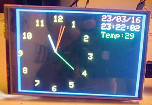
Most GPS receivers have an inbuilt patch antenna that can locate the low Earth orbit (LEO) GPS satellites very easily, even if your room’s windows are closed. As soon as two such satellites are located, the time starts appearing on the analogue dial. At the same time, the date, time and temperature are shown digitally on right side of the TFT display.
Temperature sensor TMP36 works on 3.3V. An LM35 can also be used instead, but for that we need a 5V DC supply.
Download Source Folder
Somnath Bera is an avid user of open source software. Professionally, he is a thermal power expert and works as additional general manager at NTPC Ltd


Electronics For You is a Bible for Electronics fraternilty.
Thank you for your valuable feedback.
where might i find the code for this clock. it does not appear to be in the article.
thanksave
d
Hi Dave, the Source Code is present at the end of the article. You can also download Source Code from here.
have a few issues with this project.
TFT screen is not drawing the background color
needs a better way to adjust time zone…. always displays wrong day
etc
The author Somnath Bera replies: Thanks for taking interest in the project.
In response to first point. All the figures are drawn using -Adafruit_GFX.h and most of the texts are written over and above a background color. Like tft.setTextColor(YELLOW,BLACK); This is just to remove the previously placed text to have the dynamic effect of placing one text above the another. You are not able to draw the back ground color , that means not been able to use the tft in a proper way.
You must first try with some example codes of the example folder of the Mcufriend_kbd folder GLUE_Demo_480x320 or other GLUE_Demo folders.
In response to second point. For this you can use an array like x[100] = “x”,”y”,”z”,”a”,”b”,”c”,”d”…… for each zone one correction will be applicable. The zones will be based on the lat & lon readings taken from the signals.
Then based on lat & lon , the zones will be defined and then based on zone the associated correction will be applied. The clock local time will be a very dynamic one floating across the globe for a real globe trotter !
Hi ,
Thank you very much for publishing this exciting project. I have got the clock working but small issue the hour hand and minute hand blinks with every second. Do you think its my tft shield? or is there a way to refresh the tft faster with coding?
Also I live in Melbourne Australia is there way to update the daylight saving time automatically? We go utc +10 hours on first sunday of april and the utc + 11 on the first sunday of october.
I am new to arduino and if anyone can help how to add automatic dst to this clock that will be great.
Thank you so much
The author Somnath Bera replies: There is minor flicker with every second not a blink. The flicker is not visible at all from distance [2 to 3 meters] Please check the stability of voltage on the board. Use a good quality 5V supply [1 amp or more] Put some capacitors – 470 MFD or 500 MFD across the voltage bus.
Once you have all the basis data like dd,mm,yy hh,min,ss , day and day-of-week [dow] this can be achieved. Use one more if statement on top of the time corrections… where I used 5 hours 30 minutes for IST corrections. For finding out first Sunday of the month …
When (dd >0 and dd0 and dd<=7 and mm==10 and DOW==0 ) that is the first Sunday of October month Here you put hh=hh+11;
…
After this the normal hh corrections will be placed.
The above logic may be placed suitably in two if statements and your objective will be achieved.
The ‘if’ statement will work but how long ? Is not defined… Therefore, One more ‘if’ statement to be used within the first if statement… if(mm<10) hh=hh+10;
Same for the next correction to be taken care…
How can I add a 2.8 inch screen and what changes should I make to the code.Thanks.
The author Somnath Bera replies:Please provide the pin up of the 2.8 inch display.
The displays are hooked up as per their wire diagram.The display I used then was an 8 bit about 16 wires connections.It takes more GPIOs but it’s faster for a slow atmega328 mcu.
In your case if the display is spi interface , then the wire connections will be different.
The library header will also be different.
Apart from display connection & header file, the remaining graphix program will be same without any shade of doubt.
Regards