


 Presented here is the design of a low-cost Gauss meter using a linear Hall effect sensor and a standard alkaline battery. A Gauss meter is used to measure the strength of a magnetic field. Here, in order to make sure that the meter readings are stable over the life of the battery, a low-drop fixed voltage regulator is used, which supplies a steady DC power source to the Hall effect sensor.
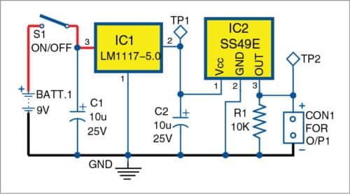
Circuit diagram of the Gauss meter is shown in Fig. 1. It comprises a compact (6F22) 9V battery (BATT.1), an LM1117-5.0 (IC1) that takes +9V from the battery through the toggle switch (S1) and regulates it to +5V for the SS49E Hall effect sensor (IC2), a 2-pin connector (CON1) for connecting a good-quality digital voltmeter (DVM) or digital multimeter (DMM). Voltage at test point TP1 is 5V when switch S1 is closed and voltage at TP2 depends on the position of magnet with respect to sensor (IC2).
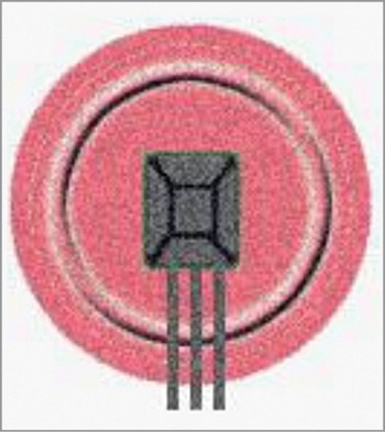
The Hall effect sensor (SS49E) is like a flattened TO-92 transistor (Fig. 2) in appearance. To give it mechanical robustness, you can glue (epoxy) flat side of the sensor to a piece of small circular plexiglass or cardboard (Fig. 3). Solder its leads to a 3-core cable and link up the cable to your main circuitry (Fig. 1).

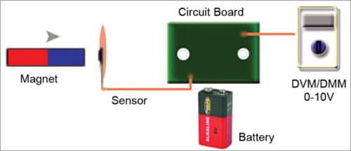
To measure the field strength of a magnet, keep it away from sensor, place the probes of DVM across CON1 and note down the output voltage (usually this quiescent output voltage is around ½ Vcc). Next, move the magnet towards the sensor. Test set up for the project is shown in Fig. 4.
You will observe two output voltages in DVM depending on the position of the magnet with respect to the sensor. If voltage read in DVM is at its highest, it means the sensor is facing towards south pole of the magnet. If voltage read is at its lowest, it is facing towards magnet’s north pole.
To measure the magnetic field strength (magnetic flux density) in Gauss, the relationship is:
Magnetic Flux Density (B) = 1000 ×(V1-V2)/k Gauss
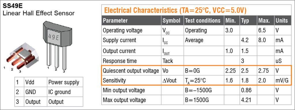
where V1 is the output voltage with no magnet near the sensor, and V2 is the output voltage with magnet near the sensor. Note that, V1 should be around 2.5V. V2 will increase if sensor is near south pole of the magnet and decrease if it is near north pole. k is the typical sensitivity (mV/G) of the sensor as indicated in its datasheet.
For example, let us say you measured 2.50 Vdc for V1 and 1.35Vdc for V2. Then,
B=1000×(2.50–1.35)/1.80=638 Gauss
It indicates north pole because the result is positive.
But if you measured 3.50 Vdc for V2 with the same sensor, then,
B=1000×(2.50-3.50)/1.80=–555 Gauss
This indicates south pole because the result is negative.
T.K. Hareendran is a freelance technical author and circuit designer, founder and promoter of TechNode – Protolabz
