


 This low-cost, simple, reliable, and effective circuit for a doorbell works without touching.
It can be quite useful in our post-Covid-19 world as it minimises the spread of virus through doorbells.
Circuit and working
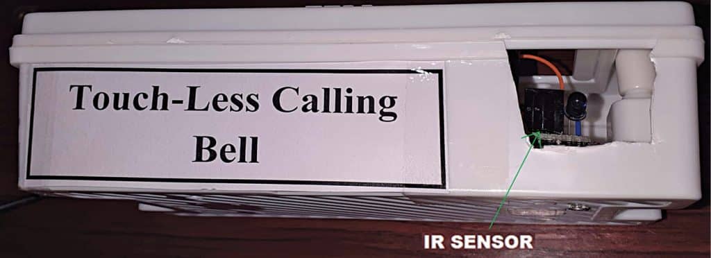
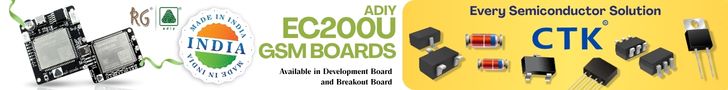
The author’s prototype is shown in Fig. 1. Fig. 2 shows the block diagram of the touchless doorbell circuit while Fig. 3 shows the complete circuit. The circuit is built around dual timer NE556 (IC1), transistor BC547 (T1), IR receiver TSOP1738 (IRRX1), IR transmitter LED (IRTX1), 5.1V Zener diode (ZD1), rectifier diode (D1), and 12V single-changeover relay (RL1).


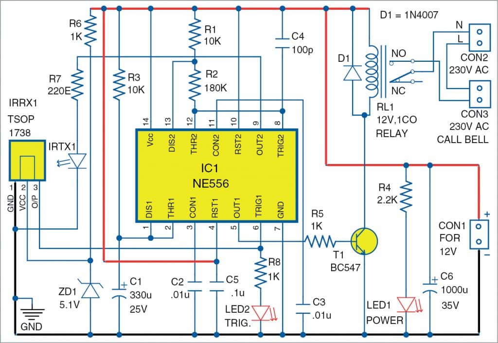
NE556 is a dual NE555 timer IC capable of producing precise time delays or oscillation. It has two independent timers. One timer is configured as an astable multivibrator (built around pins 8 through 13), which is used to drive the IR sensor circuit, and the other as a monostable multivibrator (built around pins 1 through 6) to drive the relay circuit.
The output pin 5 of IC1 is used to drive the relay, which extends AC power to the doorbell. The whole circuit is powered by a 12V DC power supply, which can be an SMPS based power supply with current rating of 500mA, or any other regulated power supply.
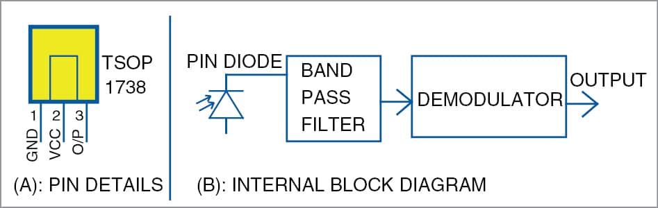
The circuit operates as a proximity sensor and detects nearby objects without any physical contact. When you place your hand or finger near infrared (IR) LED IRTX1, its IR light is reflected back and received by the nearby placed TSOP1738 sensor (IRRX1). As shown in block diagram of the sensor in Fig. 4, it has a PIN diode, pre-amplifier, band-pass filter, and demodulator. The epoxy package is designed as an IR filter.
The IR transmitting LED (IRTX1) is connected to output pin 9 of the first timer section of NE556 (IC1). This multivibrator generates the frequency in the range of 32kHz to 38kHz, which is the operating frequency of the TSOP1738 sensor. The astable mode is configured with resistors R1 and R2 and capacitor C4. The astable frequency calculation can be done using the relationship:
F=1.44/(R1+2xR2)C4
The frequency output obtained at pin 9 of IC1 is connected to IRTX1 LED through resistor R7, which controls the current flowing through the LED. The IR light emitted is proportional to this current. The value of R7 can be changed to adjust the proximity range of the system. The forward voltage of IRTX1 is around 1.9V. Zener diode ZD1 connected in series with resistor R6 is used to generate 5.1V DC, which drives the sensor.
In the monostable multivibrator section (pins 1 through 6), resistor R3 and capacitor C1 provide the necessary timing. Here the timing (on state) is around three seconds. The timing calculation is given by the relationship:
T=1.1xR3xC1
When reflected IR beam is received by the sensor, its output pin 3 becomes low. This output goes to trigger pin 6 of IC1 (monostable multivibrator section). The monostable output becomes high when a low signal is received at its trigger pin 6. The output pin 5 of IC1 is connected to the base of transistor T1 through resistor R5. Transistor T1 conducts when output pin 5 of IC1 goes high.
Relay RL1 connected to collector of transistor T1 energises when the transistor conducts. Thus, transistor T1 switches the relay on/off depending on the signal received. The doorbell is connected across the relay contacts as shown in the circuit diagram. Doorbell rings when the relay energises.
LED1 is used as a power on indicator and LED2 connected to pin 6 of IC1 through R8 is used as output signal indicator.
Construction and testing
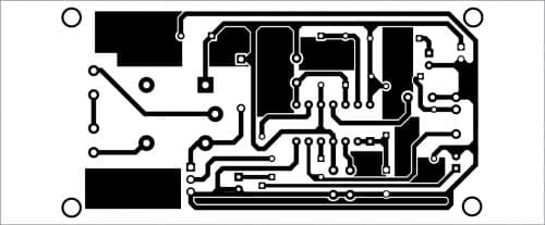
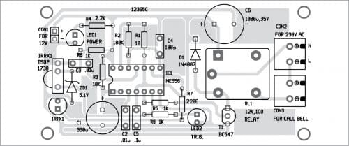
An actual-size PCB layout for the doorbell is shown in Fig. 5 and its components layout in Fig. 6. After assembling the circuit, connect the 12V across CON1, 230V AC mains across CON2, and 230V AC doorbell across CON3.
Download PCB and Component Layout PDFs: click here
Enclose the circuit in a suitable box. Fix IRTX1 and IRRX1 sensors near each other facing towards the user, as shown in the prototype. When you keep your finger in front of these sensors, the transmitted IR beam is received by sensor TSOP1738 to trigger the doorbell.
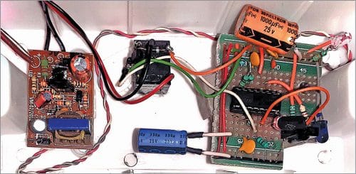
Before assembling and installing the doorbell, you may refer to author’s assembled circuit shown in Fig. 7. On the left side is 12V SMPS circuit and on right side is the main doorbell circuit. Both the circuits are enclosed in a plastic cabinet.
We have also designed the touchless Arduino doorbell that only rings when hands are sanitized.
K. Murali Krishna is currently working as a junior engineer (telecom), BSNL, Rajahmundry, Andhra Pradesh. He is an electronics enthusiast, circuit designer, and technical articles writer.

Hello Sir/Madam, I am interested in building this project, but I’m unable to download the pcb & component layout pdf through my browser. It will be very helpful if you help me by sending me the pcb & component layout pdf.
Sent on your email.
How, can you send me the PDF too. [email protected]. Thanks in advance.
Hi, you can save this page as PDF and save.
[email protected]
Please send me the documentation
The pcb shown here is mirror image. Pls check before trying.
i need to know software requirements specifications of this project if you can clear this to me
Your software requirement is not clear. This is a hardware based project.
Hello Sir/Madam, I am interested in building this project, but I’m unable to download the pcb & component layout pdf through my browser. It will be very helpful if you help me by sending me the pcb & component layout pdf
Shared with you via email.