


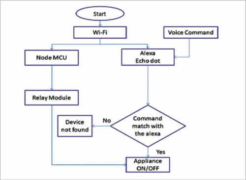
 This project presents a voice based home automation system that can be used by differently abled people, geriatrics, and the others to control home appliances and thus convert a non-smart home into a smart home. To achieve this in a simple way, Amazon Echo is used to communicate with the circuit to control the appliances.The controller used for the automation in this project is NodeMCU. When a command is given by the user to Alexa, NodeMCU gets the information through Wi-Fi and decides the switching action to be taken with respect to the electrical appliances connected to it through relays.
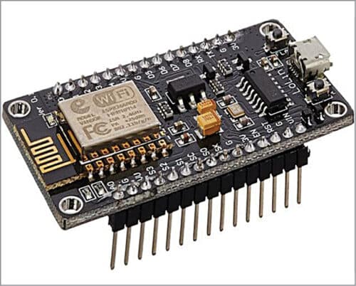
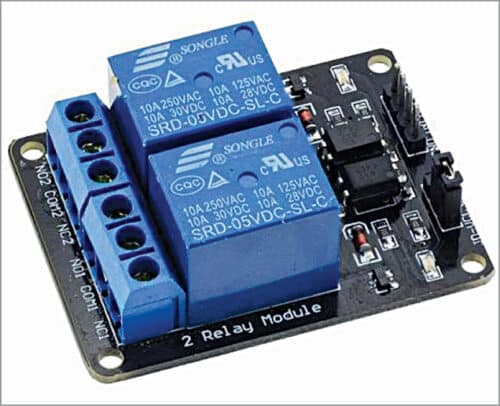
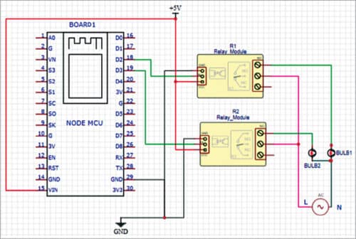
Main components used in the project are shown in Fig. 1 through Fig. 3, while circuit diagram of the home automation system using Alexa is shown in Fig. 4. NodeMCU used as the controller board is pre-programmed to connect with the Wi-Fi network and then take the commands from Alexa to perform the tasks as per instructions in the code, like turning on or turning off the lights or fans.

Connect input pins IN1 and IN2 of the 2-channel relay to digital pins of the NodeMCU as per the code. If you are controlling pins D2 and D3 of NodeMCU using Alexa, then the relay IN pins should be connected to the same D2 and D3 pins.

The ground pin in NodeMCU and the relay are connected similarly; the Vcc pin of relay is connected to Vin of NodeMCU. Vcc and GND pins of NodeMCU are connected to external 5V DC supply. One terminal of the appliance is connected directly to the relay (normally open) and the other is in series with 220V AC supply and the relay pin (common).
| Bill of Material | ||
| Components | Description | Quantity |
| Amazon Alexa Eco Dot | Alexa based smart speaker | 1 |
| NodeMCU | Microcontroller board | 1 |
| 5V, 2-relay module (R1, R2) | 1A, 110V-220V AC relays | 1 |
| B1, B2 | 230V AC, 60W bulbs | 2 |
| Wires | Female to female jumper wires | 4 |
Software
The software used for this project is Arduino for the microcontroller and Sinric from Alexa app to interface with the hardware. Install the Arduino software and then install the necessary boards required for NodeMCU, as shown in Fig. 6.

Next, copy the below link and paste it in Boards Manager: Link
Click OK to close the preference tab. Go to Tools and Board, select Board Manager, and navigate to ‘esp8266 by esp8266 community’ and install the software for Arduino from there.
We are now ready to program our NodeMCU with Arduino IDE. So, now we need to set the Sinric to get our Alexa and NodeMCU connected to each other.
Install Alexa app in your Android or iOS and complete the setup of Amazon Alexa. Open Chrome or Firefox and copy the link www.sinric.com, which on clicking appears as shown in Fig. 7.

Register for a free account and login into this account. There you can find your API key, which is unique, and options to generate smart home devices.
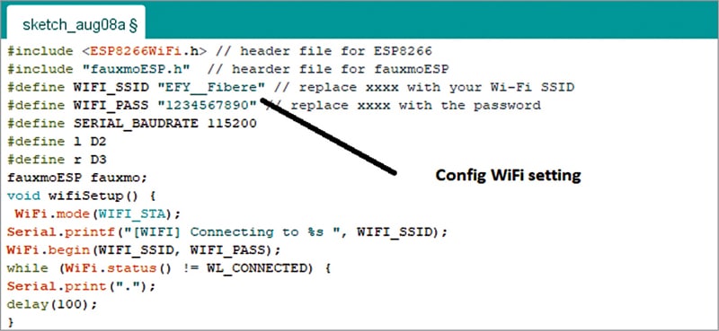
Create the code for NodeMCU. Open the .ino code file (check source.efymag.com) and then configure the Wi-Fi SSID and password of your home network. In the code, select the NodeMCU board and upload the code to the board. Image of the code snippet setting Wi-Fi and password is shown in Fig. 8.
Construction and testing
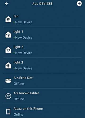
Next step is to interface the NodeMCU with Amazon Alexa Eco. Start discovering the devices by saying “Alexa discover devices.” The discovered devices will get displayed in the app, as shown in Fig. 9. Please ensure that the Wi-Fi SSID and password for NodeMCU and Wi-Fi to which Alexa is connected are the same.
Now, we can send commands to Amazon Echo. Alexa will respond to the following commands:
“Alexa, turn on light 1”
“Alexa, turn off light 1”
“Alexa, turn on light 2”
“Alexa, turn on light 2”
“Alexa, turn on light 3”
“Alexa, turn off light 3”
“Alexa, turn on fan”
“Alexa, turn off fan”
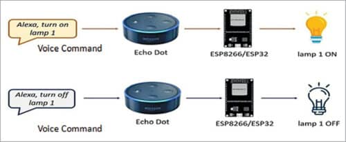
When you say “Alexa, turn on light 1,” the esp8266 will trigger a relay to turn on light 1. When you say “Alexa, turn off light 1,” the esp8266 will send a signal to the relay to turn off light 1, as shown in Fig. 10. This works similarly for light 2, light 3, and the fan.

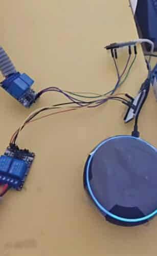
Fig. 11 shows how to give command to Echo Dot, Fig. 12 and Fig. 13 show the light’s status (off and on) before and after giving the commands to Alexa.

Download Source Code
N.M. Sai Krishna, Assistant Professor at BVRIT Hyderabad College of Engineering for Women, is an IoT and Embedded Systems enthusiast. R. Priyakanth, Associate Professor at the same college is an IoT, Embedded Systems, and Signal Processing enthusiast. A. Pranava is final year student at the college.