


 This project describes the implementation of a voice-controlled robotic car using Arduino. In this project, the user gives specific voice commands to the robot through an Android app installed on the smartphone. At the receiving side, a Bluetooth transceiver module receives the commands and forwards them to the Arduino on the robotic car.
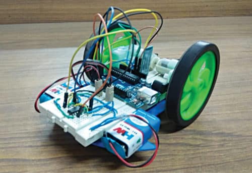
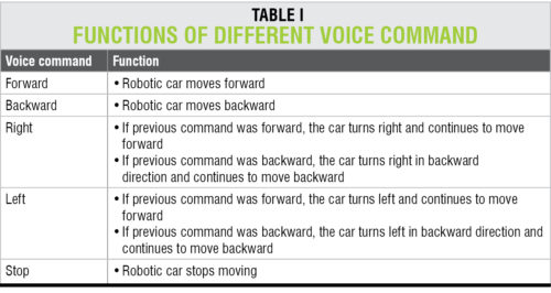
Arduino controls the movements of the robot according to received commands. The robot moves forwards, backwards, left and right, and stops according to the voice commands forward, backward, left, right and stop, respectively. The authors’ prototype of the voice-controlled robotic car is shown in Fig. 1.
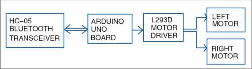
The system consists of a transmitter (Android smartphone) and a receiver (robot). Block diagrams of the transmitter and receiver sides are shown in Figs 2 and 3, respectively.
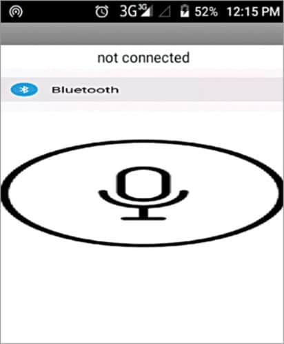
Screenshot of the home screen of Voicecontrol app is shown in Fig. 4.


Circuit and working
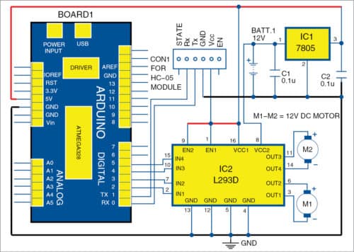
The circuit diagram of the receiver side of the robot is shown in Fig. 5.
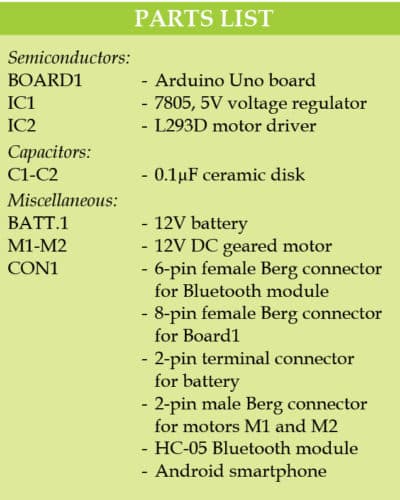
Major components used in this project are described below.

Android smartphone with app. Android speech-recognition app (voicecontrol.apk) used here was developed using MIT App Inventor. When the app is running in the smartphone, user’s voice commands are detected by the microphone present in the phone.
Commands are processed, and speech-to-text conversion is done within the app using Google’s speech-recognition technology. Text is then sent to the receiver side (that is, robotic car) via Bluetooth.
Arduino Uno R3. Arduino Uno is an AVR ATmega328P microcontroller (MCU)-based development board with six analogue input pins and 14 digital I/O pins. The MCU has 32kB ISP flash memory, 2kB RAM and 1kB EEPROM. The board provides the capability of serial communication via UART, SPI and I2C. The MCU can operate at a clock frequency of 16MHz. In this project, digital I/O pins 2, 3, 4 and 5 of Arduino are configured as output pins. Pins 0 and 1 of Arduino are used for serial communication with HC-05 Bluetooth module.
Text received via Bluetooth is forwarded to Arduino Uno board using UART serial communication protocol. Arduino program voice_ctrl.ino checks the text received and, if it is a matching string, Arduino controls the movements of the robot accordingly. Voice commands used for controlling the robot and their functions are shown in Table I.
HC-05 Bluetooth module. HC-05 module is an easy-to-use Bluetooth Serial Port Protocol (SPP) module, designed for transparent wireless serial connection setup. Serial port Bluetooth module has a fully-qualified Bluetooth V2.0+EDR (enhanced data rate) 3Mbps modulation with complete 2.4GHz radio transceiver and baseband.
Hardware features. These are:
- Typical -80dBm sensitivity
- Up to +4dBm RF transmit power
- 3.3V to 5V I/O
- Programmable input/output (PIO) control
- UART interface with programmable baud rate
- Integrated antenna
- Edge connector
Software features. These are:
- Slave default baud rate: 9600; data bits: 8; stop bit: 1; parity: no parity
- Auto-connect to the last device on power as default
- Permits pairing device to connect as default
- Auto-pairing pin: 1234 as default
Pin description. HC-05 Bluetooth module has six pins, as detailed below.
Enable. When enable is pulled low, the module is disabled. This means the module will not turn on and will fail to communicate. When enable is left open or connected to 3.3V, the module is enabled, that is, it will remain on and communication will also take place.
Vcc. Supply voltage 3.3V to 5V.
Gnd. Ground pin.
Txd and Rxd. These pins act as UART interface for communication.
State. This pin acts as the status indicator. When the module is not connected to or paired with any other Bluetooth device, the signal goes low. At this low state, the onboard LED flashes continuously, which denotes that the module is not paired with another device. When this module is connected to or paired with another Bluetooth device, the signal goes high. At this high state, the onboard LED blinks with a constant delay of, say, two seconds. This indicates that the module is paired.
L293D motor driver. This is a dual H-bridge high-current motor driver IC. It is used here because digital pins of Arduino cannot source enough current to drive the motors of the robotic car. H-bridges are also useful in controlling the direction of rotation of a motor. Enable pins 1 and 9 of the IC, being active high, are connected to 5V. Four output pins of L293D IC are connected to motors M1 and M2 on the receiver side.
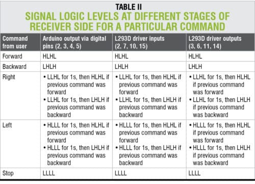
Signal logic levels at the different stages of the circuits for proper controlling of the robotic car are given in Table II.
Arduino IDE 1.6.5 is used for programming Arduino in this project. Steps to program Arduino are as follows:
- Select the proper COM port and board from Tools menu in the IDE.
- Upload source code voice_ctrl.ino to the board.
Construction and testing
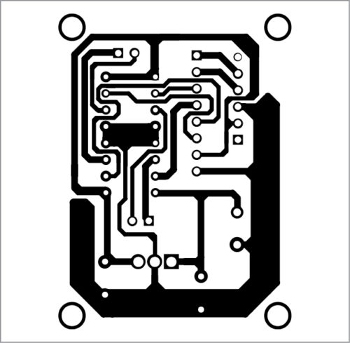
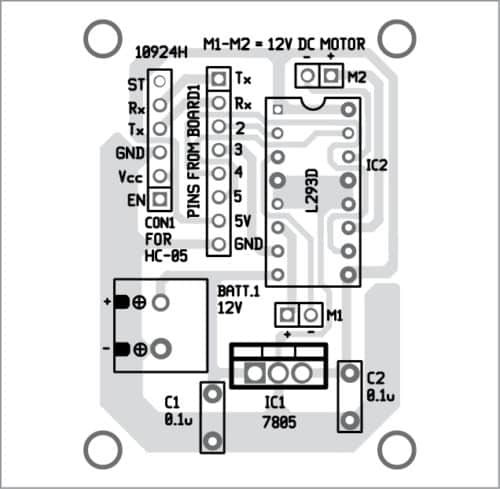
A PCB layout of the receiver circuit for Voice-Controlled Robotic Car is shown in Fig. 6 and its components layout in Fig. 7. A Micromax Q372 Android smartphone with Android Lollipop 5.0 was used to run Voicecontrol app. After successful installation of the app, turn on the Internet connection and Bluetooth of the smartphone.
Download PCB and component layout PDFs: click here
Download Source Folder
Power on the receiver circuit and pair Bluetooth module with the smartphone. Default passkey is 1234. After successful pairing, open the installed app in the smartphone and press the pushbutton with Bluetooth text and logo on it. Now, the list of paired devices will appear. Select HC-05 from the list to connect the smartphone with HC-05 Bluetooth module on the receiver side. After successful connection, ‘connected’ will be displayed on the main screen of Voicecontrol app. Press the pushbutton with microphone symbol and a prompt will appear asking for voice commands.
When the prompt appears, voice commands are detected by the app, which converts them into text and sends it to the receiver side wirelessly via Bluetooth. On the receiving side, Arduino checks the text. If it is a matching string, it controls the movements of the robot according to the description given in Table II.
Saikat Patra is passionate about electronics and MCU-based embedded system applications
Shibendu Mahata is M.Tech (gold medalist) in instrumentation and electronics engineering from Jadavpur University. He has previously worked in Reliance Industries Ltd and CSIR-CMERI. He is interested in designing MCU-based real-time embedded signal processing and process control systems.

Robot car controlled by Voice concept explained nicely. Learnt a lot and know, I am implementing it in a minor project in SGSITS, Indore. Thanks a lot.
Thank you for your feedback.