


Traditional doorbell systems often require extensive wiring, intricate assembly, and the expertise of a qualified electrician for installation. In contrast, wireless doorbells offer a simpler installation process compared to their wired counterparts.
With a lack of complicated wiring, a wireless call bell can be easily installed by anyone within a household.
This article demonstrates the process. Here we incorporate an encoder and decoder for the creation of a wireless call bell system.

POC Video Tutorial In English:
POC Video Tutorial In Hindi:
Table of Contents
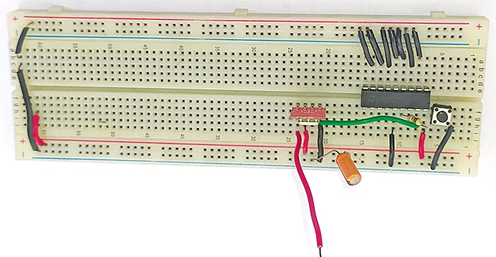
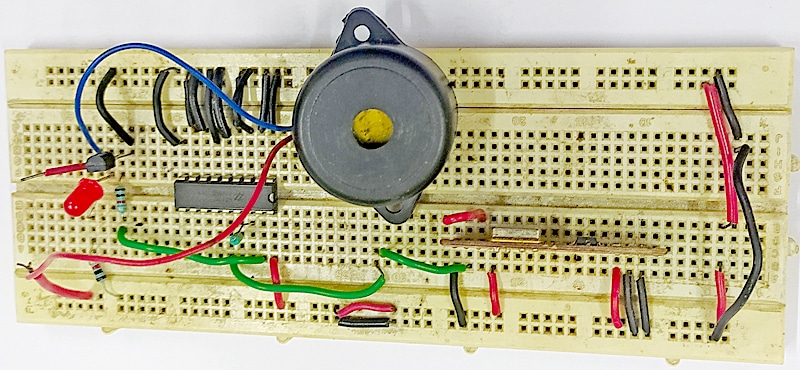
The prototypes for the author’s transmitter and receiver are depicted in Fig. 1 and 2 respectively.
| Parts List | |
| Semiconductors: | |
| IC1 | -HT12E encoder |
| IC2 | -HD12D decoder |
| T1 | -BC547 npn transistor |
| LED1 | -5mm LED |
| Resistors (all 1/4-watt, ±5% carbon): | |
| R1 | -1-mega-ohm |
| R2 | -33-kilo-ohm |
| R3, R4 | -1-kilo-ohm |
| Capacitors: | |
| C1, C3 | -100μF, 16V electrolytic |
| C2 | -0.01μF ceramic disk |
| Miscellaneous: | |
| S1 | -Push-to-on switch |
| S2 | -On/off SPST switch |
| CON1, CON2 | -2-pin connector |
| TX1 | -433MHz RF transmitter |
| RX1 | -433MHz RF receiver |
| PZ1 | -Buzzer |
| ANT.1, ANT.2 | -25-30cm wire |
| Optional: | |
| RL1 | -5V, SPDT relay |
| D1 | -1N4007 rectifier diode |
| CON2, CON3 | -2-pin connector |
| -230V based call bell | |
Wireless Call Bell – Circuit Diagram
This wireless call bell utilizes a 433MHz RF transmitter and a receiver in two separate modules. The transmitter facilitates the transmission of a 433MHz RF signal, while the receiver is responsible for receiving the signal.
Transmitter
The transmitter employs an encoder IC in conjunction with a switch, enabling the activation of the call bell. Fig. 3 illustrates the circuit diagram for the transmitting unit.
The circuit features an encoder HT12E (IC1), a 433MHz RF transmitter (TX1), and other essential components. The encoder HT12E encodes the transmission signal, with its address data encoding set via the active low address pins (A0 through A7) of encoder IC1.
The address pin of the encoder corresponds to that of decoder IC2 in the receiver unit.

Mismatched addresses between the encoder and decoder prevent signal reception. When switch S1 is momentarily pressed, the Dout (pin 17) emits a signal (data) through the RF transmitter (TX1). This encoded data is subsequently received by the receiver unit.
Receiver
The receiver employs a decoder IC along with a buzzer for signal reception sent by the transmitter. The circuit diagram of the receiver unit is depicted in Fig. 4.
The circuit includes a 433MHz RF receiver (RX1), decoder HT12D (IC2), npn transistor BC547 (T1), buzzer (PZ1), and other relevant components.

Upon receiving data through the RF receiver module (RX1), the receiver unit sends the data to DIN (pin 14) of decoder IC2.
When the address pins (A0 through A7) of both the encoder (IC1) and the decoder (IC2) match, pressing switch S1 on the transmitter results in the VT (pin 17) of decoder IC HT12D going high following the reception of RF signals.
Consequently, the transmitting unit enables the receiver buzzer to sound.
Working and Functioning
To set up the wireless call bell for operation, follow these steps:
- Begin by assembling the transmitter and receiver units separately.
- Provide power to both units.
- Momentarily press switch S1, which directs almost the entire 5-volt Vcc to the transmitter circuit.
- This 5V voltage powers the encoder IC HT12E and the RF transmitter module (TX1).
- TX1 then transmits signals to RX1, which decodes these signals and forwards them to decoder IC2.
- As a result, pin 17 of IC2 becomes active, causing transistor T1 to conduct.
- This action generates a buzzing sound from the buzzer and simultaneously makes the LED flash.
For enhanced sound intensity, consider the following:
- The receiver circuit in Fig. 4 produces a relatively low sound volume due to the buzzer used.
- To achieve a louder sound, you can incorporate an optional circuit illustrated in Fig. 5.
- To do this, replace the buzzer circuit (located within the dotted line box on the right side of Fig. 4) with the optional circuit shown in Fig. 5.
- Connect points A and B from Fig. 5 to Fig. 4 after removing the buzzer circuit.
- Finally, link a 230V AC call bell across CON4 to achieve a much louder sound.

Upon pressing switch S1, the TX1 module transmits signals to RX1, which then decodes the signals, sending a response to decoder IC2. Consequently, pin 17 of IC2 becomes high. Transistor T1 conducts, energizing relay RL1.
This, in turn, supplies power to the 230V AC call bell through the common and normally open (NO) contacts of the relay, resulting in a louder sound.
PCB Circuit Design
An actual-size, single-side PCB for the transmitting unit is shown in Fig. 6, with its component layout in Fig. 7. Assemble the unit within an appropriate enclosure and affix it to one side of the gate.


An actual-size, single-side PCB for the receiving unit is shown in Fig. 8 along with its component layout in Fig. 9.
Assemble this unit within a suitable enclosure and position it on the opposite side of the gate or inside the house from where the bell can be heard from anywhere.
It can be kept anywhere within the range of an RF transmitter. It is important to note that no PCB is designed for the optional circuit diagram.


Both units operate at 5V. Employ an antenna for both the transmitter and receiver, using approximately 15-20cm of single-strand hook-up wire.
Step-by-step Instructions to make this Wireless Call bell
Check the video given below, in which we explained the step-by-step circuit connection and how this bell will work.
Other DIY Doorbell Projects
- Wireless Doorbell
- Touchless Arduino Doorbell
- Multi-User Call Bell For Up To Nine Persons
- Remote Controlled Wireless Doorbell
- Smart Touch Display Multi-Door Doorbell System
- Musical Touch Bell
If you are looking for any other DIY, then check out our 1500+ interesting DIY Projects.
S.C. Dwivedi is an electronics enthusiast and circuit designer at EFY

Sir,
Thank you for the useful project.
In the parts list
IC2 mentioned as HD12D decoder IC.
IC2 should be HT12D decoder.
Thx.
Thanks for detecting this error and sharing with us.
Regards