

An open-hardware test platform combines measurement, switching, and device-testing functions on a modular PCB costing about $790.
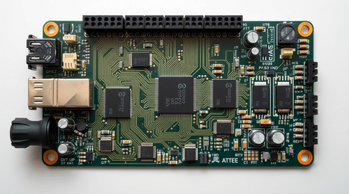
Automated testing of electronic assemblies often relies on industrial equipment that can cost tens of thousands of dollars. A research team from Universidad Autónoma de Ciudad Juárez has developed an open-hardware alternative designed to provide in-circuit and functional testing capabilities at a lower cost. The Electrical Testing Board costs about $790 to build and is intended for electronics prototyping, education, laboratories, and small-scale manufacturing.
The four-layer FR-4 board measures 187 × 160 mm and uses an 88-pin gold-finger connector for backplane integration. Its design is divided into three boards: a main PCB containing the functional test circuitry, a relay PCB for signal switching, and a pluggable microcontroller board. The controller uses a Microchip PIC32MX795F512L running at 80 MHz, while two PIC18F4620 microcontrollers control the relay matrices and auxiliary inputs and outputs.
The system provides 16 test nodes connected through relay-based switching buses. These nodes can route signals between programmable power supplies, measurement circuits, comparators, pull-up and pull-down networks, and protection circuitry. The relay network enables automated testing cycles in the range of 10 to 50 milliseconds per device.
The onboard measurement circuitry can measure voltage from 0 to 100V, current from 1µA to 1mA, resistance from 0.5Ω to 1MΩ, and capacitance from 10nF to 220µF. Voltage measurement uses a 16-bit successive-approximation ADC with a precision reference, while current measurement uses multiple calibrated gain stages. Resistance is measured using a ratiometric voltage-divider method, and capacitance is determined by monitoring the charge and discharge of the device under test.

Testing against reference instrumentation showed voltage measurement errors below 1 per cent at the higher test points, while resistance measurements remained below 1 per cent error from 1kΩ to 1MΩ. Lower resistance and capacitance values showed larger deviations, highlighting the limitations of the low-cost measurement approach.
The board can communicate with a host computer or programmable logic controller through RS-232, opto-isolated UART, or Ethernet. Up to 12 boards can also be connected to a single host controller, allowing multiple devices to be tested in parallel.
The platform is not intended to replace high-end industrial automated test equipment. It supports one device under test per board, has 16 test nodes, operates over a practical bandwidth of DC to 10kHz, and does not support measurements such as inductance or IEEE 1149.1 JTAG boundary scanning.
The hardware is released under the CERN Open Hardware Licence v2.0, with firmware under the GNU General Public Licence v3.0 and documentation under Creative Commons Attribution 4.0. The researchers have made the design files, schematics, firmware, and bill of materials available for replication and modification.